15
GB
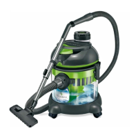
A. Engine’s set. This section includes an engine, a switch and operating elements. Upper
part of this section constitutes HEPA filter used to filter out dust and other small parts from
the air that is blown out. Under a foam filter there is a big, plastic float which, as the container
fills up, raises and cuts off vacuum at the same time informing about a necessity to empty the
container.
A1 – Switch
A2 – HEPA filter case
A3 – HEPA filter
A4 – Cover of HEPA filter case
A5 – Indicator of filter pollution level
A6 – Float chamber
A7 – Foam filter
A8 – Case with a clamp
B. Container. The container section is a middle part of the vacuum cleaner, used as a contain-
er to collect dust and dirty water. This section is attached to engine’s set with clamps.
B1 – Water container
B2 – Water filter tank
B3 – Water filter sponge
B4 – Water filter tube
B5 – Clamps
B6 – Sucking inlet
B7 – Wheels
B8 – Rubber gasket
C. Hose. This section includes a sucking hose with a handle and sucking tubes. Sucking at-
tachment is connected with container’s set through putting the hose into sucking inlet. Suck-
ing tube is connected to a handle. The handle has sucking power regulation. The hose can be
put on engine’s set with the use of hanger.
C1 – Sucking hose
C2 – Handle
C3 – Sucking power regulation
C4 – Connecting element
C5 – Telescopic sucking tube
C6 – Hanger
C7 – Floor and carpet head
D. Additional accessories.
D1 – Handle used to fasten accessories
D2 – Attachment for cracks
D3 – Round brush
D4 – Venetian blinds cleaner brush
D5 – Air freshener