Testing.
Warning.
Toavoidelectricshockorinjury,ordamagetotheIPC,a
All6LEDsmustlight.
Conclusion
CorrectFunctionInverterOutputs: all6LEDsmustlight.
lwaysdisconnectpowersuppliesbeforemakingor
disconnectingconnections.Waitthreeminutesforstoredchargeincapacitors(DCVoltage)tosafely
discharge.
ThisInverterPhasetestmustbecarriedoutwiththecompressordisconnectedfromtheInverterBoard.
4
4
4
4
4
4
4
Disconnectthe3phasessupplyingthecompressor.
ConnectL1,L2andL3oftheIPCtothe3phasesoutputfromtheinverterboard(sometimesdesignatedU,V,W).
Afterallconnectionsaresafelymade,switchonthepower.
CleartheIPC-307memoryandcheckbatteryconditionbypressingandholdingtheMEMswitchfor4secondsuntil
abeepisheard. The6LEDSwilllightinsequence.Releasetheswitch.
Configurethesystemtocallforcooling
Assoonastheinverterinitiatesastartupsequence,correspondingLEDswillblinkinasequence(notindicativeof
rotationdirection)andanaudiblebeepwillsound.Normallythisonlyoccursforasecondorso. TheIPCwillnotifyof
astartupsequencehavingbeendetectedbysoundingasingleshortaudiblebeepevery4seconds,corresponding
LEDswillflashindicativeofvalidsignalssensed..
PresstheMEMbuttontorecalltestresult. HoldMEMtoclearmemoryforre-testing.Ifone
ormoreLEDsarenotlit,checkprobeconnectionsandrepeattest.
FaultyOutput: one,moreoralloftheLEDsdonotlight.
FaultyOutput: oneormoreLEDsareconstantlyon.
Ifanyoralloftheoutputsarenotfunctioningproperly,thentheInvertorboard(orIPM)willneedtobereplaced.
TherearevariouswaysofconnectingtheInverterPhaseChecker,dependingonthetypeandaccessibilityofthe
terminals.TheEngineermustensurethatsuitableandsecureconnectionsarecorrectlymadebeforeswitchon.
ExampleofconnectingtheIPC-307
totheInverterCompressorfeed Terminals
L1(U)
L2(V)
L3(W)
+
ACIN RECTIFI-
CATION
DC
VOLTAGE
OUTPUT
TRANSISTORS
ACMOTOR
3PHASEINVERTER
InverterInformation.
Theinverterusesarectifiertoconverttheincomingalternatingcurrent(AC)todirectcurrent(DC)andthenswitchesthe6
transistorsinasequencetoproduce ACofadesiredfrequency. Thevariablefrequency ACdrivesthecompressor.
Whenaninvertersystemstartsup-Itiscommonfortheretobeadelayoftypicallytwotothreeminutesbeforetheoutput
isenabledandthedurationoftheoutputswitchingsequencethatfollows,mayonlylastforasecondormore.
Thesequenceisterminatedoncetheinvertersensesthereisnocompressorloading.
Insomecasesthephasesequencemightberepeatedfollowingafurtherdelay. Also,followingafault,somesystemswill
requirearesettingactionofsomekind.
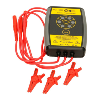
IntroductiontotheIPC-307
Battery Powered
Operation
Memory
Magnetic Base
Compressors.
TheIPCfunctionstoidentifyinverterfaultswhenaproblemarisessuchascompressorover-currentprotectionandshut
down.Itsensesandmeasuresvalidswitchingoperationofthe6outputtransistorsininvertersystems. A sequencein
whichall6transistorsswitchbothonandoff,isindicativeofcorrectoperation. TheIPCisconnectedtotheinverter
insteadofthecompressorandautomaticallymonitorstheinverteroutput.
The IPC remains in standby mode and will start automatically when inverter activity is sensed on the L1,2 & 3 inputs, or
when the MEM button is pressed.
Virtually no power is consumed while in standby. The battery can be tested by holding the MEM button for 4 seconds: If
6 LEDs light, then the batteries are good.
When testing is complete, clear memory to put the IPC into standby mode and save battery power.
The IPC will record and display any valid signals it detects with LED and an audible beep. Valid signals are recorded in
memory and will remain until cleared.
Following 4 seconds of no activity, the IPC will notify of a start up sequence having been detected by sounding a single
short audible beep every 4 seconds. Corresponding LEDs will flash indicative of valid signals sensed.
This will continue for 18 minutes, after which the memory will be cleared and the IPC enters standby mode.
Inverter start up sequences are often very short in duration - only a second or more. So the IPC stores valid signals in
memory for later observation.
Memory is recalled at any time by momentarily pressing the MEM button to display which signals have been detected.
All 6 LEDs constantly lit indicated a test pass.
Holding the MEM switch for 4 seconds or longer will clear memory and place the IPC in standby mode.
The memory must be cleared before initiating any test or repeat test.
The IPC-307 has a strong magnetic base for mounting conveniently on to steel condenser housings.
Compressorscanfailwithinsulationbreakdownbetweenmotorwindingsordowntoearth.Itisadvisedtocarryoutan
electricalinsulationtesttoearthandaresistancetestbetweeneachwindingofthecompressor,inaccordancewith
manufacturer’sdata,priortoreconnecting.
+ + +
- - -
 Loading...