Do you have a question about the MR MESSKO TRASY MT-ST160F and is the answer not in the manual?
All personnel involved in installation, commissioning, operation or maintenance must be qualified and observe instructions to prevent injury or damage.
Pointer thermometers measure temperatures on power transformers, reactors, or similar equipment; observe limit values.
Comply with national health and safety regulations, especially for live parts and electrical installation.
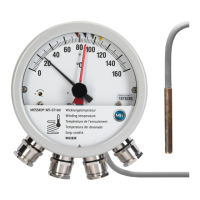
Pointer thermometers with adjustable microswitches for oil temperature indication; mechanical system requires no power input.
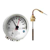
Attach thermometer to transformer using mounting plate, ensure vertical installation and avoid vibrations/EM fields.
Route capillary tube carefully, avoiding kinks, do not bend or pull; store excess tube at max 60°C.
Insert sensor into thermowell, fill with oil/paste, tighten using M16 gland; refer to other manuals for combi/transmitter types.
Fit kick protection to thermowell adapter and route capillary tube inside it.
Maximum pointer records max reading; reset using the knob.
Connect microswitches by flipping cover plate, preparing cables, and wiring to terminal strip as per diagram.
Set microswitches by sliding by hand; check by turning pointer clockwise past switches and back.
Diagram showing installation dimensions and components of the pointer thermometer.
Technical information on cable gland components and assembly according to EN 60423.
| Type | Bimetallic thermometer |
|---|---|
| Immersion length | 100 mm |
| Process connection | G 1/2 |
| Scale division | 2 °C |
| Protection class | IP65 |
| Accuracy class | Class 1 |
| Accuracy | ±1 % |
| Material | Stainless steel |