Routine Operation 3-45MTX5000 User and Technical Manual
Note
This procedure should be performed following
initial installation of the MTX5000 System with a
Standard ODU, after replacement of the IDU or
Standard ODU, or following any repairs to the
cable assembly providing power from the IDU to
the Standard ODU.
Note
In the following procedure, option buttons may be
selected using either the touch screen or the
function keys and the SEL key.
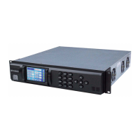
1. Verify the ODU status indicator does not indicate a
major fault (indicator is not red). See Figure 3-87.
Figure 3-87: Main Screen - Typical
Channel 1 0Offset
Antenna Ant. Pol.Antenna1 H
RFU2
7US
RF Band
Preset A
Analog
4.83 & 5.8, 3MHz Vid Dev
RF Output
XX
dBm
<- Status
Setup
Status ->
PA On
SUM
ODU
IDU
RF
L/R
H
L
Setup Option
Button
RF Band
Option
Button
ODU Status
Indicator
Notes
If your MTX5000 system is a single band system,
go to step 5.
If your MTX5000 system is a dual band system,
perform step 2 thru step 12 for both bands.
2. Select the RF Band option button and observe the RF
Band screen is displayed and the current RF band
option button is highlighted. See Figure 3-88,
Figure 3-89 on page 3-46, Figure 3-90 on page 3-46,
or Figure 3-91 on page 3-46.
Figure 3-88: RF Band Screen - Typical
2GHz Change Plan
RFU2
RFU1
RF Band
Main
PA On
SUM
ODU
IDU
RF
L/R
H
L
Main Screen
Option Button
RF Band
Option
Buttons