Your locomotive will slow at a steady rate. If your throttle was left at a setting
other than 0, releasing the brake button will cause the locomotive to gradually
accelerate to the speed determined by the throttle setting (as long as the
momentum is in the “ON” position). Pushing the brake will allow for a more
gradual deceleration.
Throttle Control: Is used to set the speed of the locomotive. With the
momentum button in the OFF position, your locomotive will immediately
accelerate to the speed dictated by the throttle. In momentum ON, however, the
brake should be applied slowing the locomotive. If the brake is not applied, but
the throttle is turned down, the train will gradually coast to a stop.
Indicators:
Overload Indicator: In the event of a short circuit or overload, the circuit
protector will trip. Both of your direction indicator LEDs will light, and flash
alternately giving a visual indication of a problem. See point 4 for further
instructions.
Terminals:
Variable DC: These terminals are for the attachment of your Throttlepack 9900
to the mainline of your layout. If the direction of your locomotive does not match
the position of your direction LED’s, simply reverse the wires going to these
terminals.
Accessories DC: These terminals supply DC voltage for use with accessories.
Be careful to observe polarity when hooking up accessories. The output of the
accessories DC voltage will be determined by the position of the scale/gauge
switch, located on the bottom of the cabinet.
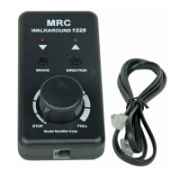
Walk Around Plug: Located in the front of the cabinet is a plug for the optional
tethered handheld with memory. (MRC Part No. 0001315).
Your new Throttlepack 9900 comes with a built in universal power supply
that can be used safely in both inside and outside the U.S.A., (120 VAC/60
Hz or 220VAC/50Hz). For use outside the U.S.A. please replace the wall cord
with one suitable for your type of wall outlet.
For your safety-Plug the wall cord firmly into the rear of the cabinet, before
plugging it into a wall outlet.
Make sure that the green four terminal right angle plug is firmly inserted into the
rear of the cabinet. Using a small flat-bladed screwdriver, attach two wires (18
AWG or heavier) from the Main Track layout to the terminals marked “TRACK”,
and two wires from any of your accessories to the terminals marked “ACC”.
Strip the wire approx. 1/8 inch, and insert it into each of the plug gates facing you
and then tighten the screws securely.
Note: When connecting to any terminal, care must be taken that wires do not
touch more than one terminal at a time. Loose wires are a danger to your unit
and layout. Be certain wires are properly wrapped around terminals before
tightening screws. Also note that the output terminal screws can get hot during
periods of peak use.
1. Never reverse a locomotive without stopping it first. To do so may damage the
locomotive motor.
3 THROTTLEPACK 9900

 Loading...