Do you have a question about the mru AIR fair OPTIMA 7 and is the answer not in the manual?
Provides general safety information and precautions for MRU products, stressing manual review before initial use.
Defines safety categories (DANGER, WARNING, CAUTION, ATTENTION, NOTE) and their meanings for user awareness.
Details essential guidelines for safe operation, handling, and maintenance to prevent hazards and damage.
Offers key insights into the analyser's capabilities, limitations, and expected sensor lifespan for informed usage.
Outlines critical instructions for the safe handling, charging, and use of the internal rechargeable lithium-ion battery.
Defines the analyser's primary purpose for short-term emission control measurements and its non-application as safety equipment.
Presents background on MRU GmbH, its history, and its expertise in developing high-quality emission monitoring analysers.
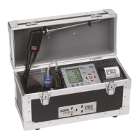
Advises retaining original packaging materials for protecting the unit during transit or potential returns to the factory.
Clarifies MRU GmbH's responsibility to accept hazardous waste, such as sensors, for proper disposal.
States MRU GmbH's policy for accepting analysers delivered after August 2005 for compliant disposal.
Illustrates the analyser's internal gas flow system, highlighting the extraction probe and electrochemical sensors.
Details the physical components and connection ports of the analyser, made from fibre-reinforced plastic.
Explains the function, disassembly, and maintenance of the condensate separator, including safety warnings for acidic condensate.
Showcases two variants of extraction probes (fixed and exchangeable) with their respective components and connections.
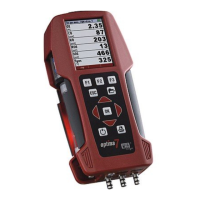
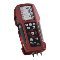
Describes the analyser's display interface, including the menu bar, function key bar, and status indicators.
Explains the function and operation of each key on the analyser's keypad for navigation and control.
Outlines the analyser's main menu system (Measurement, Storage, Extra) and the functions accessible within each.
Guides users through initial setup: unpacking, manual review, battery charging, and date/time verification.
Details how to configure instrument-specific parameters via the 'Settings' menu for personalized operation.
Instructs on adjusting measurement settings like temperature unit, pressure unit, draft unit, and core flow search.
Covers configuration for printer type, print options (SHORT/LONG), and including site information on printouts.
Explains Bluetooth configuration for data exchange with external devices like smartphones, printers, or large-scale modules.
Provides instructions for setting the analyser's date and time, noting automatic summer/winter time changes.
Guides users on setting up measurement programs, including CO limit, fuel types, and display window configurations.
Details how to set a CO limit to protect the CO sensor from high concentrations during measurements.
Explains selecting fuel types and setting the O2 reference, crucial for accurate combustion calculations.
Guides users on creating and defining custom fuel types with their specific parameters for personalized use.
Explains how to customize the display of measured values in the analyser's three measurement windows.
Describes how to configure the zoom window to display specific pairs of measured values for detailed viewing.
Details how to rename measurement programs for better organization and identification within the analyser's menus.
Explains how to power the analyser using its internal battery or external charger, and connection safety.
Describes the automatic shut-off feature that deactivates during active measurements or battery charging cycles.
Covers connecting to mains power for charging and operation, including the switch to trickle charge mode.
Explains how to interpret the battery status symbol and the analyser's low battery behaviour and shutdown.
Details the analyser's operational temperature range and behaviour outside this range, including warning messages.
Provides instructions for checking and maintaining the condensate separator, including filter status and safety for acidic condensate.
Emphasizes checking all connections, hoses, and gas path tightness for accurate and safe operation.
Guides users through the automatic zero-point setting process, essential for accurate gas measurements.
Instructs users on selecting a measurement program, with safety warnings regarding toxic gases and exhaust outlets.
Explains the core flow search process to find the optimal measurement point by identifying maximum flue gas temperature.
Details how measurement values are organized and displayed, including direct, calculated values, and potential error indicators.
Describes the draft measurement feature, its availability, and how it can be re-enabled after disabling.
Explains how to set a CO limit and how exceeding it changes the CO value display colour.
Details the CO-purging function, its activation for sensor protection, and deactivation methods.
Describes the analyser's response to high CO/H2 levels, including colour changes and the option to switch off the purge pump.
Outlines the 'Test program' designed for testing facilities and test gases, showing only measured values.
Guides users through the 'Ambient CO Test' procedure for measuring ambient CO concentration, emphasizing pre-test zeroing.
Explains how to use the temporary buffer to store momentary measurement values for later printing or saving.
Details how to store measurement results in the data memory using function keys F2 or F3.
Instructs users on printing measurement results using the Speedprinter or other compatible thermal printers.
Explains how to stop a running measurement, freeze values, and return to the measurement menu.
Describes accessing and continuing work with the last recorded measurement values after a measurement ends.
Guides users on performing and saving pressure measurements, including changing measurement names and taking zero points.
Explains measuring and displaying two temperatures (T1, T2) and their difference using specific connectors.
Explains data storage based on sites, capacity, and adding/modifying sites using PC programs like MRU Win.
Details checking memory status, site count, and measurement types stored via the 'Memory info' function.
Covers managing sites: creating new ones, viewing existing data, modifying details, and deleting sites individually or all.
Explains using an SD card for data transfer, including importing sites from CSV files and exporting sites and measurements.
Guides viewing stored measurements, filtering by type, accessing context information, and detailed measurement data.
Describes accessing the service calibration menu, protected by a PIN, for advanced adjustments and configuration.
Explains how to reset all individual analyser settings to their original factory default values, losing custom configurations.
Details accessing service values for sensor diagnostics and troubleshooting, requiring a PIN code for access.
Guides performing a leak test using a cap to check system integrity and identify potential leaks in the gas path.
Explains how to view files on the SD card, and perform operations like deleting, refreshing, or opening files.
Details accessing analyser information like firmware version, serial number, operating hours, and service history.
Recommends regular maintenance, including annual inspection and sensor calibration by MRU service centres for optimal performance.
Explains service messages indicating required maintenance and how to acknowledge them for continued operation.
Provides comprehensive specifications for operating temperature, humidity, power, size, and measurement accuracy of sensors.
Details the analyser's calculations for air ratio, excess air, efficiency, losses, dew point, and CO/CO2 ratio.
Explains the text input interface for customizing names of fuel types, sites, and measurement programs.
Describes the analyser's prompts for user confirmation before executing critical actions like deleting data.
Guides users through updating the analyser's software using an SD card, including preparation and verification steps.
Explains using the USB port for data transfer to a PC/Laptop, including connection and initial 'mating' procedures.
Provides a systematic guide to identifying and resolving common analyser issues, causes, and solutions.
Describes additional features like the pre-filter for high dust concentrations and troubleshooting the condensate separator.
| Brand | mru |
|---|---|
| Model | AIR fair OPTIMA 7 |
| Category | Measuring Instruments |
| Language | English |