Do you have a question about the MSA General Monitors S4000TH and is the answer not in the manual?
Instructions for physically installing and connecting the Model S4000TH sensor and its components.
List of necessary tools for installation and wiring of the Model S4000TH sensor.
General Monitors' mission to provide safety solutions and product usage guidelines.
Critical safety warnings regarding toxic gas and electrostatic discharge for the S4000TH.
Procedures for verifying system integrity before and after initial power-up.
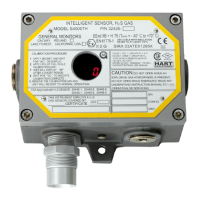
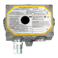
Overview of the S4000TH intelligent sensor for H2S gas detection and its features.
Instructions for checking the S4000TH upon delivery, including handling damage or discrepancies.
List of tools needed for installing the S4000TH sensor, including Allen wrench and screwdriver.
Guidelines and recommendations for selecting optimal installation locations for the S4000TH sensor.
Details on extending the sensor distance from the electronics unit using specific housings and cables.
Instructions and warnings for mounting and wiring the S4000TH, including conduit sealing and drain loops.
Details on connecting wires to the terminal blocks (TB) inside the S4000TH housing.
Instructions for connecting sensor wires to Terminal Block TB1 on the S4000TH.
Details on connecting power and signal wires to Terminal Block TB2 on the S4000TH.
Connecting the 4-20 mA analog output signal for remote display or digital conversion.
Connecting relay contacts for optional warn, alarm, and fault functions on the S4000TH.
Requirements for interconnecting cables used in EU approved applications.
Guidelines for proper cable armor, screen, and power supply connections in safe areas.
Factors influencing explosion-proof integrity and procedures for maintaining it.
Pre-start verification steps for the S4000TH system to ensure proper operation.
Procedure for initial power-up of the S4000TH sensor, including stabilization time.
Methods for resetting latched warn and alarm relays on the S4000TH after an alarm event.
Overview of configurable options for the S4000TH, including sensor range and communication settings.
Flowchart illustrating the menu structure for configuring the S4000TH sensor.
How to select and change the H2S sensor range (0-20, 0-50, 0-100 ppm) on the S4000TH.
Enabling the calibration output feature for the S4000TH, affecting the analog output during calibration.
Procedure for adjusting the warn relay settings, including energized/de-energized and latching states.
Procedure for adjusting the alarm relay settings, including energized/de-energized and latching states.
Configuration of Modbus Channel 1, including baud rate, data format, and address.
Configuration of Modbus Channel 2, including baud rate, data format, and address.
Enabling or disabling the HART communication option on the S4000TH for remote calibration.
Checking the sensor's response without activating alarms by entering Gas Check Mode.
Step-by-step guide for performing a gas check on the S4000TH sensor.
Procedures and recommendations for calibrating the S4000TH sensor.
Detailed steps for calibrating the S4000TH sensor using calibration gas.
How to abort a calibration sequence if gas has not yet been applied.
Explanation of the sensor life estimate feature and how it's updated.
Procedure for initializing the sensor life estimate after installing a new sensor.
Overview of calibration equipment available for the S4000TH.
Using breaker bottles and ampoules for introducing calibration gas to the S4000TH.
Using an H2S Portable Purge Calibrator for gas calibration of the S4000TH.
Using the Remote Gas Calibrator (RGC) accessory for calibration in difficult locations.
General maintenance procedures and warnings, including lubrication and EU approved compounds.
Guidelines for proper storage of the S4000TH Intelligent Sensor, including environmental conditions.
List of fault codes displayed by the S4000TH and instructions for resolving them.
Troubleshooting steps for F2 fault, indicating calibration failure due to no gas or excessive gas.
Troubleshooting F3 fault related to program memory changes, often caused by voltage transients.
Troubleshooting F4 fault indicating sensor lead issues or amplifier errors, requiring connection checks.
Troubleshooting F5 fault for a short-circuited sensor heater or amplifier, requiring connection checks.
Troubleshooting F6 fault due to supply voltage dropping below the operational threshold.
Troubleshooting F7 fault related to EEPROM errors, often requiring power cycling or unit return.
Troubleshooting F8 fault occurring when the unit is left in setup mode for too long.
Troubleshooting F9 fault when Gas Check Mode is active for more than 12 minutes.
Troubleshooting F10 fault related to continuous closure of remote test or calibrate switches.
Troubleshooting F11 fault indicating an internal error, possibly due to incorrect voltage values.
Contact information for General Monitors' offices in various global locations.
Selecting the baud rate for Modbus communication with the S4000TH.
Selecting the data format for Modbus communication, including parity and stop bits.
Details of the Modbus read query and response message structure for status information.
Format of the Modbus query message used to request status data from the S4000TH.
Format of the Modbus response message containing status data from the S4000TH.
Details of Modbus write query and response message formats for commands.
Format of the Modbus query message used to send commands to the S4000TH.
Format of the Modbus response message after a write command to the S4000TH.
List of Modbus function codes supported by the S4000TH for read and write operations.
Explanation of Modbus exception responses and their corresponding error codes.
Description of abnormal Modbus communication events and how the S4000TH responds.
Detailed list and descriptions of Modbus exception codes supported by the S4000TH.
Register details for 0-20 mA current output proportional to sensor reading.
Register details for reading and changing the S4000TH operational mode.
Register details for alarm state and error conditions indicated by bit position.
Register reserved for future use.
Register indicating the S4000TH model identification.
Register for reading the software revision of the S4000TH.
Register providing a block of status information including analog, mode, error, and sensor life.
Register for reading the 0-20 mA output current value.
Register for reading the S4000TH operational mode and error codes.
Registers detailing sensor errors and the remaining sensor life percentage.
Registers for the LED display, showing gas concentration, LEDs, and decimal points.
Registers containing the 32-bit serial number of the S4000TH.
Register for reading and setting alarm thresholds, latching, and energized states.
Register for reading and setting warn thresholds, latching, and energized states.
Register for setting the Modbus Com1 communication address.
Register for setting the Modbus Com1 communication baud rate.
Register for setting the Modbus Com1 data format (parity, stop bits).
Register for setting the Modbus Com2 communication address.
Register for setting the Modbus Com2 communication baud rate.
Register for setting the Modbus Com2 data format (parity, stop bits).
Register reserved for future use.
Register to reset latched alarms when gas levels are below set points.
Register for reading the current estimate of remaining sensor life.
Register for changing the H2S sensor scale and forcing recalibration.
Register indicating calibration success and controlling analog output during calibration.
Registers reserved for future use.
Register for enabling or disabling the HART communication feature.
Command to test the HART output by producing constant zeros or ones.
Command to abort the calibration process.
Counter for total Modbus communication receive errors.
Indicates bus activity rate as a percentage of the addressed node.
Counter for Modbus function code errors.
Counter for Modbus starting address errors.
Counter for Modbus RXD CRC errors (High byte).
Counter for Modbus RXD CRC errors (Low byte, same as Hi).
Counter for Modbus hardware UART parity errors.
Counter for Modbus hardware UART overrun errors.
Counter for Modbus hardware UART framing errors.
Counter for Modbus address or data errors in Channel 1.
Register reserved for future use.
Command to clear parity, framing, and overrun errors.
Command to clear Modbus communication errors.
Feature to select HART low current levels for fault indication.
Register for internal use by the S4000TH.
Registers for logging events such as faults, warnings, alarms, calibration, and maintenance.
General Monitors' warranty terms and conditions for the S4000TH sensor.
Explanation of how the S4000TH uses MOS film technology to detect H2S gas.
Technical specifications for the S4000TH sensor, including type, life, repeatability, and approvals.
Technical specifications for the S4000TH sensor, including type, life, repeatability, and approvals.
Physical dimensions, weight, and housing material for the S4000TH sensor.
Electrical requirements, power consumption, and relay ratings for the S4000TH.
Table detailing analog signal behavior in different modes (HART enabled/disabled).
Description of the S4000TH's digital display and LED indicators.
Information on the S4000TH's RS-485 output capabilities for communication.
Supported baud rates for Modbus communication with the S4000TH.
List of faults that the S4000TH monitors and reports.
Information on the S4000TH's compliance with EMC standards.
Details on HART communication compatibility and requirements.
Specifications for shielded cable and maximum distances for S4000TH connections.
Environmental operating and storage conditions for the S4000TH sensor.
Operating temperature ranges for S4000TH electronics under different classifications.
Recommended storage temperature range for the S4000TH.
Recommended operating humidity range for the S4000TH.
List of certifications and approvals for the S4000TH, including CE, CSA, FM, and HART.
Details on HART Communication Foundation approval and compatibility for the S4000TH.
Information on ordering replacement parts and accessories for the S4000TH.
List of available replacement sensors for the S4000TH, including ppm range and body material.
Part number for the universal sensor housing used with the S4000TH.
List of sensor accessories available for the S4000TH, such as mounting plates.
List of calibration equipment, including breaker bottles, ampoules, and calibrators.
List of replacement electronic and mechanical parts for the S4000TH sensor.
List of recommended spare parts, such as calibration magnets, for annual replacement.
Information regarding Factory Mutual Research Corporation (FMRC) approval for the S4000TH.
List of specific sensors approved by FMRC for use with the S4000TH.
List of related apparatus, like the DT210 module, approved by FMRC.
| Protection | IP66 |
|---|---|
| Output | 4-20 mA |
| Operating Humidity | 0 to 95% RH (non-condensing) |
| Compatibility | Compatible with various gas detectors and controllers |
| Application | Industrial gas detection |