EasyManua.ls Logo

MSD Ignition 8739 User Manual

MSD Ignition 8739
4 pages
To Next Page IconTo Next Page
Page #1 background imageLoading...
Page #1 background image
AUTOTRONIC CONTROLS CORPORATION • 1490 HENRY BRENNAN DR., EL PASO, TEXAS 79936 • (915) 857-5200 • FAX (915) 857-3344
MSD Module Selectors
Two Step, PN 8739
Three Step, PN 8737
Parts Included:
1 - Module Selector
4 - Mounting Screws
Note: Do NOT use solid core spark plug wires with any MSD component.
1 - Parts Bag, Wiring Terminals
The MSD Module Selectors provide the ability to switch between two or three different rpm or
degree modules. The different modules are activated when 12 volts are applied to the correspond-
ing activation wire. The Selectors work with either a Soft Touch Rev Control or any MSD Timing
Control that uses plug-in modules.
Module 2 This is the default module. It is active when no voltage is present
on the other wires.
Active when 12 volts are applied to the Red Wire.
Active when 12 volts are applied to the Blue Wire. (3-Step Only)
Module 1
Note: If 12 volts are applied to the Red and Blue wires at the same time, Module 3
will be active.
Module 3
ACTIVATION WIRES
SWITCH OR
MICRO SWITCH
PN 8820
TO GROUND
TO 12V
RED
BLACK
TO MODULE SOCKET
TO LINE LOCK
OR TRANS-BRAKE
SOLENOID
MODULE SELECTOR
STEP
MODULE 2 MODULE 1
PN 8739
AUTOTRONIC CONTROLS CORPORATION
1490 HENRY BRENNAN DR, EL PASO, TX 79936
TM
Figure 1 Basic Two Step Module Selector Installation.
•The 2-Step Module Selector switches between two modules.
•The 3-Step Module Selector switches between three modules.
Question and Answer IconNeed help?

Do you have a question about the MSD Ignition 8739 and is the answer not in the manual?

MSD Ignition 8739 Specifications

General IconGeneral
BrandMSD Ignition
Model8739
CategoryRecording Equipment
LanguageEnglish

Summary

MSD Module Selectors

Parts Included

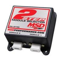
Lists components included with the MSD Module Selectors for installation.

Activation Wires

Explains how activation wires control different modules based on applied voltage.

Module Selector Wiring Diagrams

Two Step Module Selector Wiring

Illustrates the basic wiring diagram for the 2-Step Module Selector installation.

Three Step Module Selector Wiring

Details the basic wiring connections for the 3-Step Module Selector.

Advanced Three Step Configurations

Wiring to Timing Control for Retards

Shows wiring a 3-Step Module Selector to a timing control for multiple retard functions.

Wiring to Shift Light for Shift Points

Illustrates wiring a 3-Step Module Selector to a shift light for multiple shift points.

Technical Support and Warranty

Service and Repair Information

Provides instructions for returning MSD components for service and repair.

Limited Warranty Details

Outlines the terms and conditions of the limited warranty for MSD Ignition products.