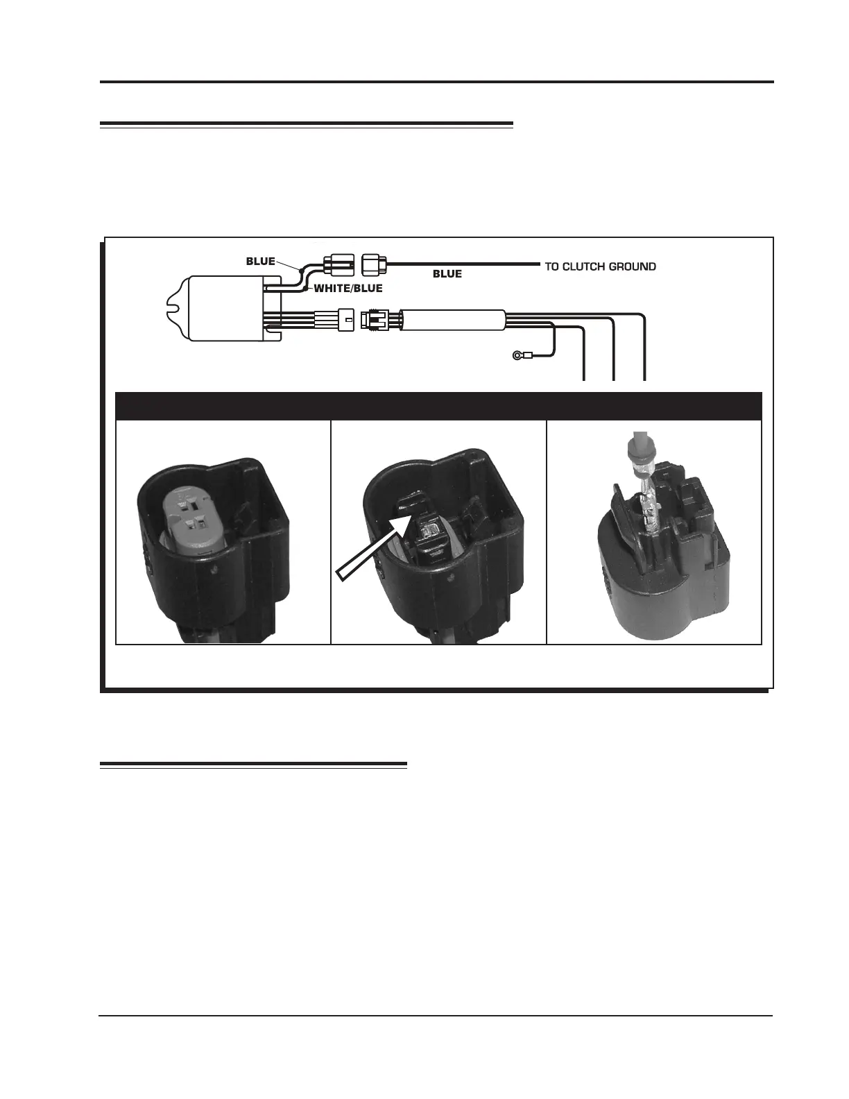
Figure 2 Wiring the Launch Activation Wire.
CONNECTING THE LAUNCH WIRE
Most motorcycles have a clutch switch that provides a ground when the clutch is engaged. This is
the default wiring of the Launch Master. If you prefer to activate the launch limit with 12 volts, disas-
semble the 2-pin connector and move the Blue wire to align and connect with the White/Blue wire
(Figure 2).
CONFIRM INSTALLATION
With the power ON, activate the clutch switch. When everything is correct, the LED will illuminate. To
verify the rpm, set the limit at a lower rpm, such as 3,000, and test the system.
If the engine has trouble starting or running, check the following:
• Ground connection
• Coil connections
Note: Due to safety controls on some applications, the launch rpm limit may be activated when the
bike is in neutral or when the kickstand is down.
Lift and remove the purple lock
with a small screwdriver.
Lift the tab and pull on pin
to remove.
Insert Blue wire in slot 'B'.
Reinstall purple lock.
P I N S W A P F O R 1 2 V A C T I V A T I O N
FOR 12 V ACTIVATED LAUNCH
MOVE THE BLUE WIRE TO ALIGN
WITH THE WHITE/BLUE WIRE ON
THE CONTROLLER
LAUNCH
MASTER
PN 4351
TAN
TAN
RED
BLACK
GROUND
INSTALLATION INSTRUCTIONS 3
MSD POWERSPORTS
• WWW.MSDPOWERSPORTS.COM • (915) 858-3365 • FAX (915) 858-3496
 Loading...