MSD • WWW.MSDPERFORMANCE.COM • (915) 857-5200 • FAX (915) 857-3344
INSTALLATION INSTRUCTIONS
1
Parts Included:
1 - MSD Ignition
1 - Harness, PN 8860
OPERATION AND FEATURES
DIGITAL OPERATION
The Digital 6A and 6AL use a high speed RISC microcontroller to control the ignition's output while
constantly analyzing the various inputs such as supply voltage, trigger signals and rpm. The high
speed controller can make extremely quick compensations to the output voltage, multiple spark
series, timing and rpm limits while maintaining precise timing and accurate rev limiting. The circuits
and controller of the MSD have been thoroughly ltered to create protection against Electro Magnetic
Interference (EMI).
CAPACITIVE DISCHARGE
The Digital 6A and 6AL feature a capacitive discharge ignition design. The majority of stock ignition
systems are inductive ignitions. In an inductive ignition, the coil must store and step up the voltage
to maximum strength in between each ring. At higher rpm, since there is less time to charge the coil
to full capacity, the voltage falls short of reaching maximum energy which results in a loss of power
or top end miss.
The MSD Ignition features a capacitor which is quickly charged with 520 - 535 volts and stores it until
the ignition is triggered. With the CD design, the voltage sent to the coil positive terminal is always
at full power even at high rpm.
MULTIPLE SPARKS
The MSD produces full power multiple sparks for each ring of a plug. The number of multiple sparks
that occur decreases as rpm increases, however the spark series always lasts for 20° of crankshaft
rotation. Above 3,000 rpm there is simply not enough “time” to re the spark plug more than once,
so there is only one powerful spark.
PROTECTION
The Digital 6A and 6AL have a built in reverse polarity protection circuit. This will protect the ignition
in the event of wrong connections.
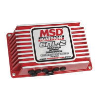
MSD Digital 6A and 6AL Ignition Control
6A - PN 6201/62013, 6AL - PN 6425/64253
1 - Main Harness
1 - Parts Bag
WARNING: During installation, disconnect the battery cables. When disconnecting the battery always
remove the Negative cable rst and install it last.
6AL ONLY
4 - Vibration Mounts
1 - Screwdriver
Note:
The Carb label supplied is required to aid in passing the California Smog Check program. This label
must be installed in an underhood location that is readily visible.
Note: If you're triggering an aftermarket EFI system with the Gray wire of the MSD, see page 5 to
deactivate the tach verication feature.
Important: When installing a Digital Series Ignition, timing will be affected, reset to your engine's
specications.
ONLINE PRODUCT REGISTRATION: Register your MSD product online. Registering your product
will help if there is ever a warranty issue with your product and helps the MSD R&D team create
new products that you ask for! Go to www.msdperformance.com/registration.