4 INSTALLATION INSTRUCTIONS
M S D I G N I T I O N • W W W . M SD IG NI TI ON .C OM • ( 91 5) 8 5 7- 52 00 • F A X (9 15 ) 85 7- 33 4 4
WIRING
Deutsch Male 4-Pin Connector
12ga Red Battery Positive – This wire connects directly to the battery positive (+) terminal or
to a positive battery junction or the positive side of the starter solenoid.
12ga Black Battery Negative – This wire connects to a good ground, either at the battery negative
(-) terminal or to the engine.
16ga Orange Coil Positive – This wire connects to the positive (+) terminal of the coil. This is the
only wire that makes electrical contact with the coil positive terminal.
16ga Black Coil Negative – This wire connects to the negative (-) terminal of the coil. This is the
only wire that makes electrical contact with the coil negative terminal.
Deutsch Female 4-Pin Connector
18ga Red Ignition – This wire is switched 12 volts to turn the ignition and modules on and off.
18ga White Trigger Input – This wire is used to communicate the timing signal from the System
Controller to the ignition.
18ga Black Ground – This wire supplies the ground for the System Controller. This connects
internally with the ground from the heavy Black wire in the first connector.
18ga Orange Battery – This wire supplies power through the Power Grid Ignition to the System
controller.
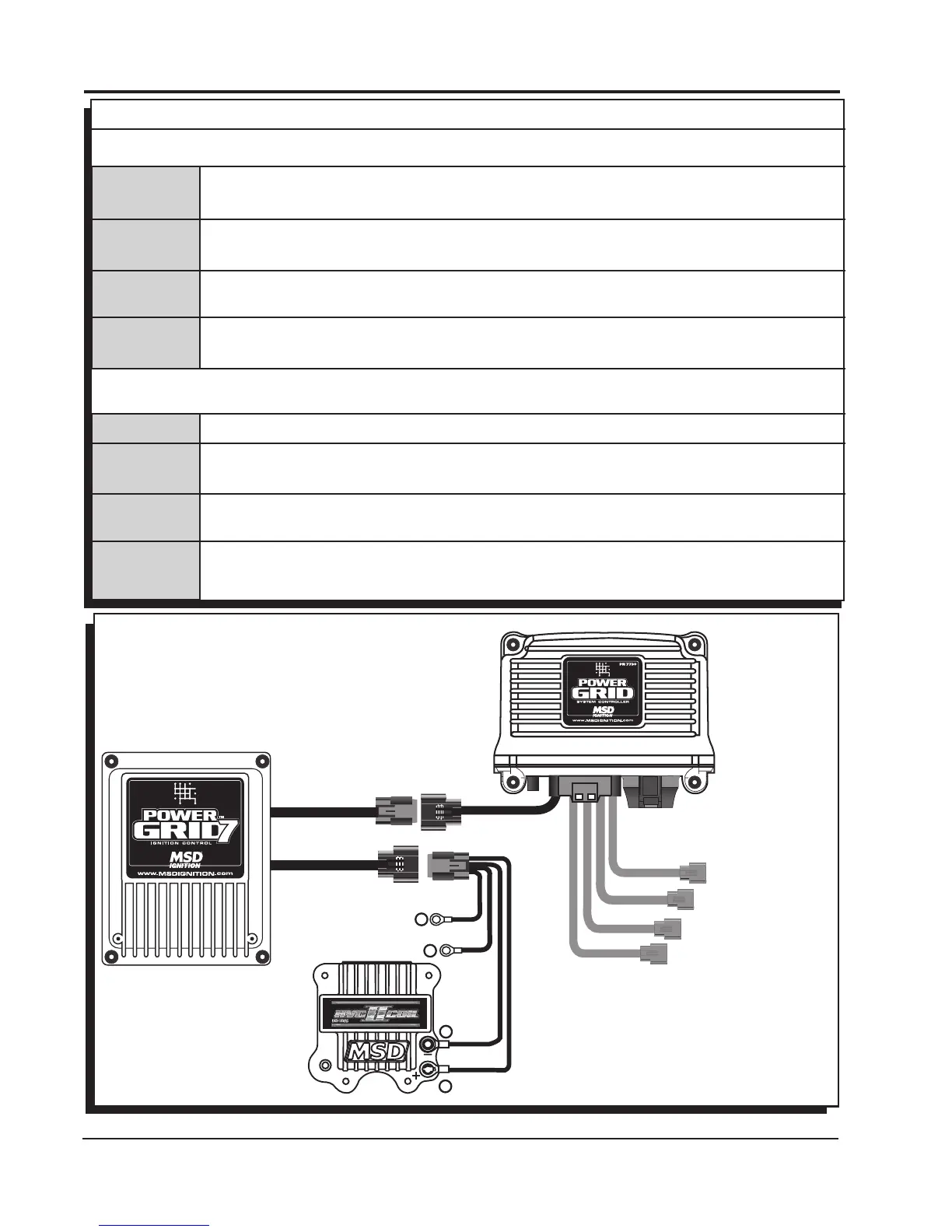
Figure 1 General Wiring
ORANGE
BLACK
+
+
-
-
TO BATTERY POSITIVE
TO BATTERY NEGATIVE
RED
BLACK
ORANGE
WHITE
HEAVY RED
HEAVY BLACK
CONTROLLER WIRES.
SEE PN 7730
INSTRUCTIONS