2-27
Hardware Setup
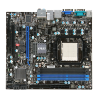
MS-7640
Chapter 2
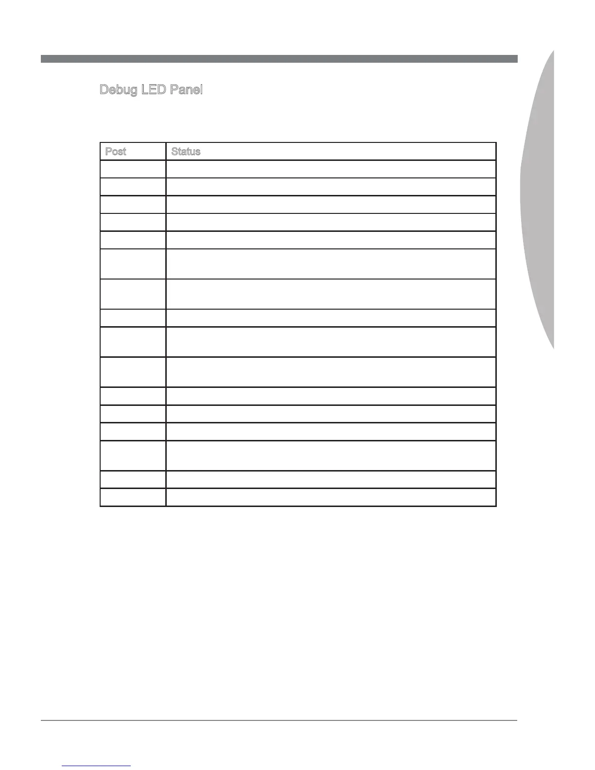
Debug LED Panel
Please refer to the table below to get more nformaton about the Debug LED mes-
sage.
Post Status
FF Power on and rst ntalze CPU.
C0, C1, C2 Early CPU Intalze.
C4, C6 Intalze chpset.
D4, D5 Intalze memory.
08 Intalze keyboard.
2A, 31 Intalze onboard devces. Load Opton ROM (VGA and RAID opton
ROM) from BIOS to memory.
37 Dsplayng sgn-on message, CPU nformaton, setup key message
and any OEM specc nformaton.
38 Intalze USB devce and derent devces.
3C Md POST ntalzaton of chpset regsters. Detect derent devces
(parallel ports, seral ports and coprocessor n CPU...etc.)
75, 78 Intalze INT 13 devces and IPL devces. (nclude SATA/ PATA HDD
and CD/DVD ROM).
87 Enter setup screen. BIOS setup f needed/ requested.
A4 Wat for user nput at conguraton dsplay f needed.
A7 Dsplay the system conguraton screen f enabled.
B1 Save system context for ACPI (Advanced Conguraton and Power
Interface).Prepare gve control to OS loader (INT 19H).
00 Pass control to OS Loader (typcally INT 19H).
AA Enter OS.
 Loading...