21
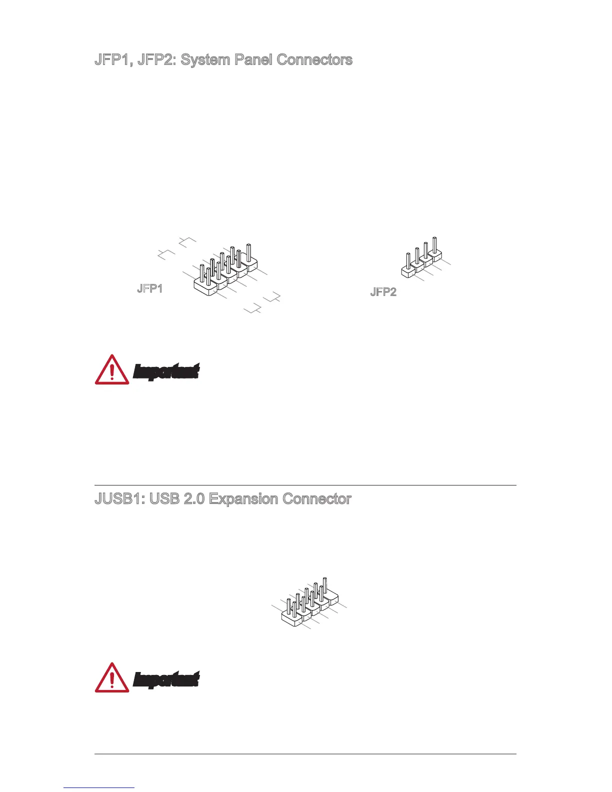
JFP1, JFP2: System Panel Connectors
These connectors connect to the front panel switches and LEDs. When installing the
front panel connectors, please use the optional M-Connector to simplify installation.
Plug all the wires from the computer case into the M-Connector and then plug the
M-Connector into the motherboard.
1.+
3.-
10.No Pin
5.-
Reset S
2.
BUZ+
Important
•
On the connectors coming from the case, pins marked by small triangles are
positive wires. Please use the diagrams above and the writing on the optional M-
Connectors to determine correct connector orientation and placement.
•
The majority of the computer case’s front panel connectors will primarily be
plugged into JFP1.
JUSB1: USB 2.0 Expansion Connector
This connector is designed for connecting high-speed USB peripherals such as USB
HDDs, digital cameras, MP3 players, printers, modems, and many others.
1
.
V
C
 Loading...