2-14
Hardware Setup
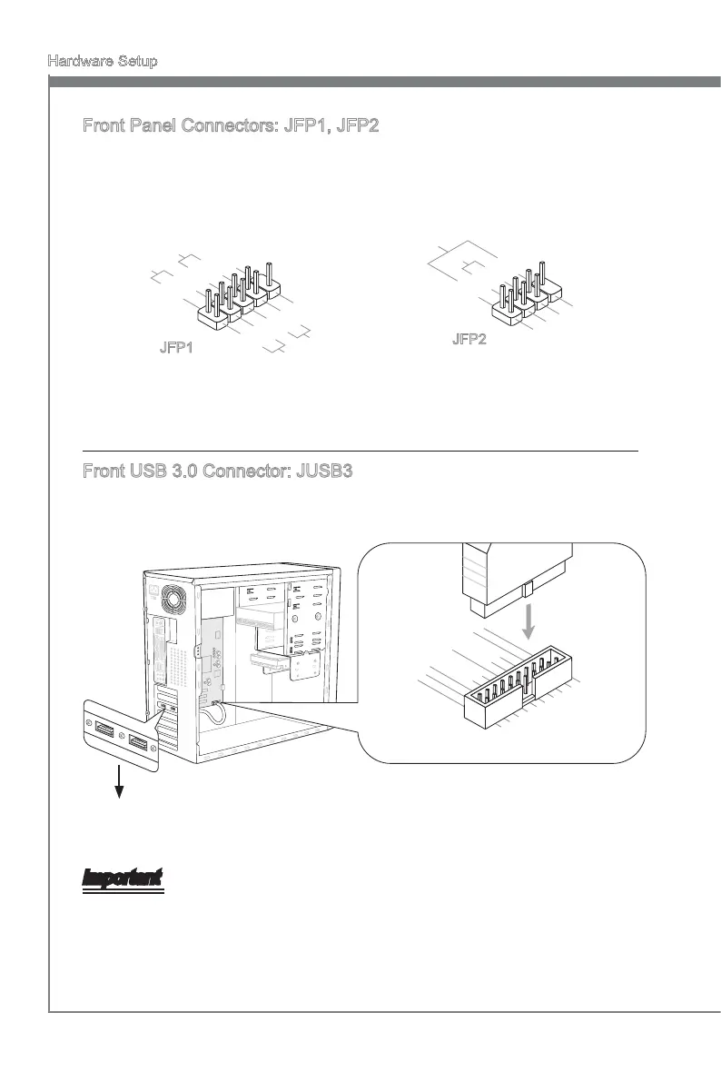
Front Panel Connectors: JFP1, JFP2
These connectors are for electrcal connecton to the front panel swtches and LEDs.
The JFP1 s complant wth Intel
®
Front Panel I/O Connectvty Desgn Gude.
1
.Ground
3.Suspend
LE
D
5.Power
LE
D
7.No
Pi
n
8.
+
6.
-
4.
+
2.
-
Buzzer
S
peaker
1.+
3.
-
10.No
Pi
n
5.
-
Reset
S
witch
HDD
LE
D
P
ower
S
witch
P
ower
LE
D
7.
+
9.Reserve
d
8.
-
6.
+
4.
-
2.
+
JFP1
JFP2
Front USB 3.0 Connector: JUSB3
USB 3.0 port s backward-compatble wth USB 2.0 devces. Supports data transfer rate
up to 5 Gbt/s (SuperSpeed).
5.
U
SB3_TX_C_DN
4
.Ground
3.USB3_RX_DP
2.USB3_RX_DN
1.Power
10.NC
9.
+
USB2.0
8.
-
U
SB2.0
7
.Ground
6.USB3_TX_C_DP
20.No
Pi
n
19.Power
18.USB3_RX_DN
17.USB3_RX_DP
16.Ground
15.USB3_TX_C_DN
14.USB3_TX_C_DP
13.Ground
12.USB2.0
-
11
. +
U
SB2.0
* The MB layout n ths gure s for reference only.
USB 3.0 Bracket (optonal)
Important
Note that the pns of VCC and GND must be connected correctly to avod possble
damage.
If you want to use a USB 3.0 devce, you must use the USB 3.0 cable to connect to
the USB 3.0 port.
•
•
 Loading...