2-16
Hardware Setup
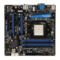
TPM Module connector: JTPM1
Ths connector connects to a TPM (Trusted Platform Module) module (optonal). Please
refer to the TPM securty platform manual for more detals and usages.
* The MB layout n ths gure s for reference only.
1
15V
10.No
P
in
14.Ground
8.5V
P
ower
12.Ground
6.Serial
I
RQ
4.3.3V
P
ower
2.3V
S
t
andby
p
ower
1.LP
C
C
loc
k
3.LP
C
R
eset
5.LP
C
a
ddres
s
&
d
at
a
p
in0
7.LP
C
a
ddres
s
&
d
at
a
p
in1
9.LP
C
a
ddres
s
&
d
at
a
p
in2
11
.LPC
a
ddres
s
&
d
at
a
p
in3
13.LP
C
F
rame
TPM module s optonal
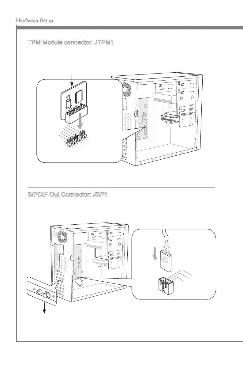
S/PDIF-Out Connector: JSP1
Ths connector s used to connect S/PDIF (Sony & Phlps Dgtal Interconnect Format)
nterface for dgtal audo transmsson.
* The MB layout n ths gure s for reference only.
S/PDIF-Out Bracket (optonal)
 Loading...