English
21
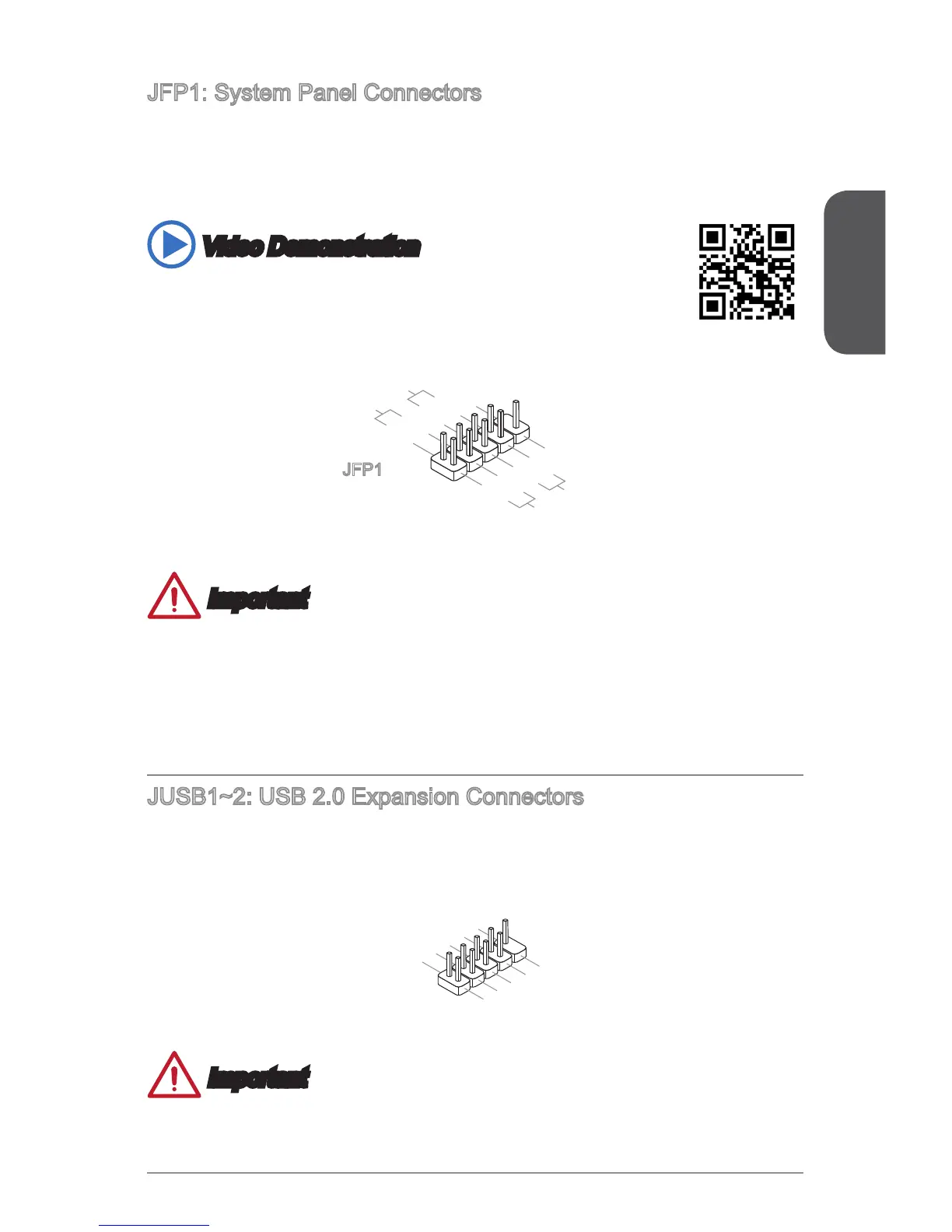
JFP1: System Panel Connectors
These connectors connect to the front panel switches and LEDs. The JFP1
connector is compliant with the Intel
®
Front Panel I/O Connectivity Design Guide.
When installing the front panel connectors, please use the optional M-Connector to
simplify installation. Plug all the wires from the computer case into the M-Connector
and then plug the M-Connector into the motherboard.
Video Demonstration
Watch the video to learn how to Install front panel connectors.
http://youtu.be/DPELIdVNZUI
1.
+
3.-
10.No
Pi
n
5.
-
Reset
S
witch
HDD
LE
D
P
ower
Switch
P
ower
LE
D
7.
+
9.Reserve
d
8.
-
6.
+
4.-
2.+
JFP1
Important
On the connectors coming from the case, pins marked by small triangles are
positive wires. Please use the diagrams above and the writing on the optional M-
Connectors to determine correct connector orientation and placement.
The majority of the computer case’s front panel connectors will primarily be
plugged into JFP1.
JUSB1~2: USB 2.0 Expansion Connectors
This connector is designed for connecting high-speed USB peripherals such as USB
HDDs, digital cameras, MP3 players, printers, modems, and many others.
1
.
V
C
C
3
.
U
S
B
0
-
1
0
.
NC
5
.
U
S
B
0
+
7
.
G
r
o
u
n
d
9
.
N
o
P
i
n
8
.
G
r
o
u
n
d
6
.
U
S
B
1
+
4
.
U
S
B
1
-
2
.
V
C
C
Important
Note that the VCC and GND pins must be connected correctly to avoid possible
damage.
•
•
 Loading...