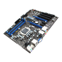
2-28
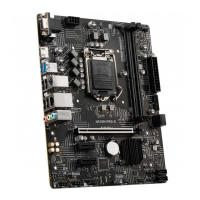
Hardware Setup
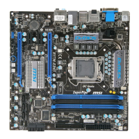
▍
MS-7637
BATT
+
SA
TA
1_2
SA
TA
3_4
SA
TA
5
SA
TA
6
SA
TA
7
IDE1
JBAT1
JCI1
JUSB3
JUSB2JUSB1
J1394_1
SYSFAN1
JTPM1
(option al)
JPWR2
JCOM
1
JLPT
1
PCI_E1
PCI_E2
PCI_E3
PCI_E4
PCI1
PCI2
JSP1
JCD1
JAUD1
JFP1 JFP2
Top :Optica l
Bottom:
SPDIF
mouse/k eyboard
Top: LAN Jack
Bottom: U SB ports
T:
M:
B:
Line-In
Line-Ou t
Mic
Top:1394
Middle:
Bottom: e
USB ports
SATA port
T:RS-Out
M:CS-Ou t
B:SS-Ou t
Top: VGA Port
Bottom: D VI-D
Top:
Bottom: H DMI
USB ports
port
DIMM2
DIMM1
DIMM4
DIMM3
CPUFAN
SYSFAN3
SYSF
AN4
SYSFAN2
JPWR1
OC Genie
Intel
H55
RE SE T
RESET
Direct OC
POWER
Led StatuS indicatorS
APS LEDs
These APS (Actve Phase Swtchng) LEDs ndcate the current CPU power phase
mode. Follow the nstructons
below to read.
: ON, : OFF
4 of the LEDs wll lght blue when CPU s n 4 phase power mode.
3 of the LEDs wll lght blue when CPU s n 3 phase power mode.
2 of the LEDs wll lght blue when CPU s n 2 phase power mode.
1 of the LEDs wll lght blue when CPU s n 1 phase power mode.
APS LEDs
 Loading...