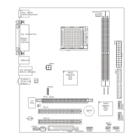
Front USB Connector: JUSB1
This connector, compliant with Intel
®
I/O Connectivity
Design Guide, is ideal for connecting high-speed USB
interface peripherals such as USB HDD, digital
cameras, MP3 players, printers, modems and the like.
CD-In Connector: JCD1
This connector is provided for external audio input.
L R
Front Panel Audio
Connector: JAUD1
This connector allows you to connect the front
panel audio and is compliant with Intel
®
I/O
Connectivity Design Guide.
(2)GND
VCC5
Line_JD(10)
(2)GND
MIC_R
Front to Sense
Front Panel Connectors: JFP1,
JFP2
These connectors are for electrical connection to the
front panel switches and LEDs. The JFP1 is compliant
with Intel
®
Front Panel I/O Connectivity Design Guide.
Chassis Intrusion Connector: JCI1
This connector connects to the chassis intrusion switch cable. If the
chassis is opened, the chassis intrusion mechanism will be activated.
The system will record this status and show a warning message on the
screen. To clear the warning, you must enter the BIOS utility and clear
the record.
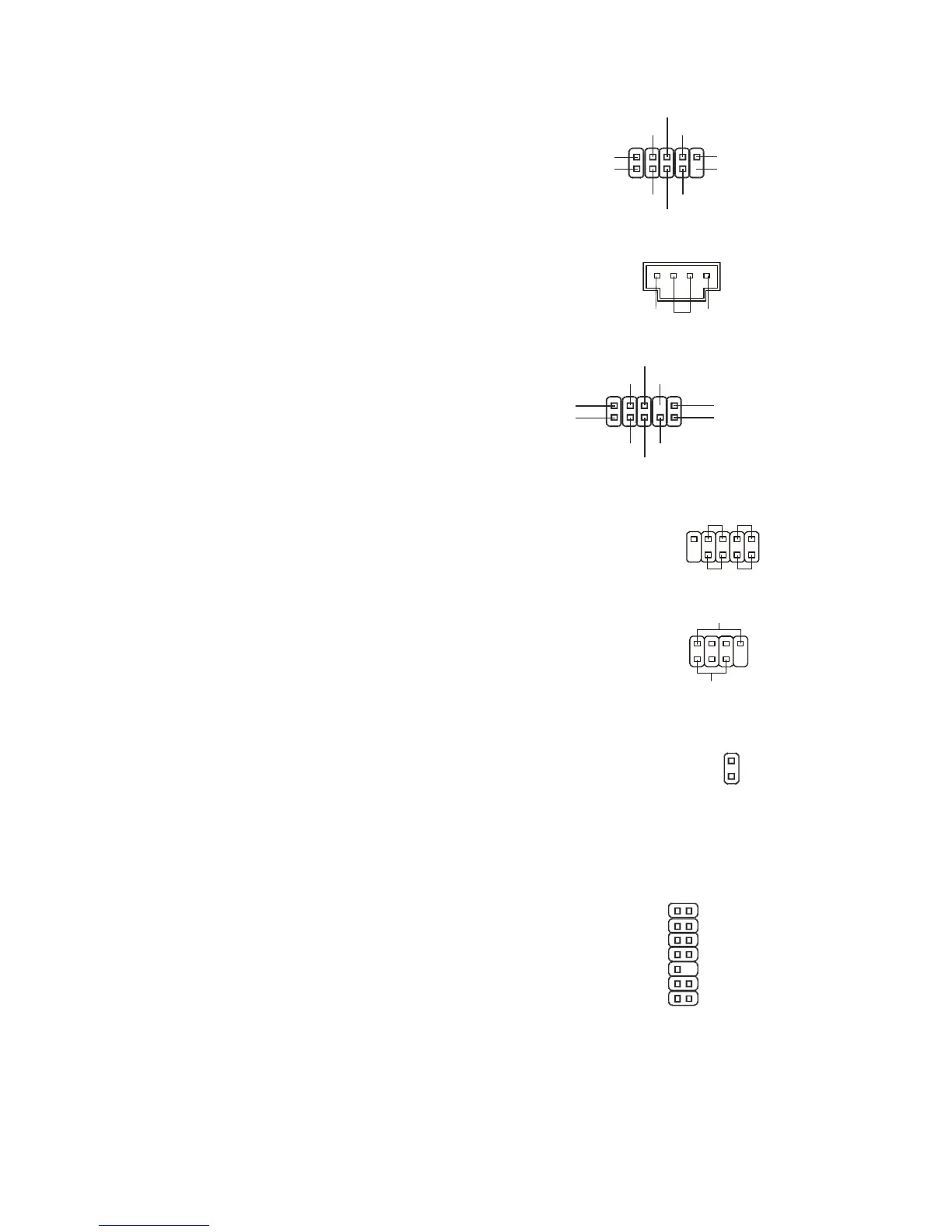
TPM Module Connector: JTPM1
(optional)
This connector connects to a TPM (Trusted Platform
Module) module (optional).
KEY
GND
GND
LRST#
LAD0
LAD1
LAD2
LAD3
LFRAME#