Do you have a question about the MSI K9VGM-V Series and is the answer not in the manual?
Details FCC limits for Class B digital devices and protection against harmful interference.
States that unauthorized modifications can void user's authority to operate equipment.
Specifies use of shielded cables and AC power cord for emission limits.
States material is intellectual property of MICRO-STAR INTERNATIONAL.
Lists registered trademarks belonging to their respective owners.
Documents the revision history of the manual.
Lists 12 instructions for safe equipment handling and operation.
Warns about explosion danger if battery is replaced incorrectly.
Advises collecting waste batteries separately for recycling or special disposal.
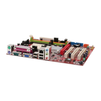
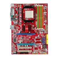
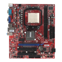
Introduces the K9VGM -V Series mainboard and its features.
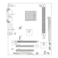
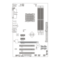
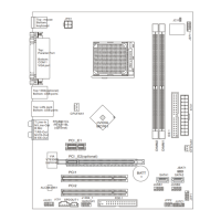
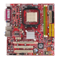
Diagram showing the physical layout of the mainboard components.
Details CPU, Chipset, and Main Memory specifications.
Covers Slots (PCI-E, PCI) and Storage (IDE, SATA) interfaces.
Lists external and internal connectivity ports.
Describes Audio codec, LAN controller, and BIOS.
Specifies Micro-ATX form factor and mounting holes.
Covers CPU socket, installation, and cooler mounting.
Warns about overheating and provides overclocking caution.
Step-by-step guide for inserting DDR II memory modules into slots.
Details connection for the ATX 24-pin power supply.
Provides 12V power to the CPU.
Covers FDD1 for floppy drives and IDE1/IDE2 for hard drives/CD-ROMs.
Details two SATA interface ports for hard disk drives.
Covers CD-ROM audio connector (JCD1) and SPDIF digital audio interface.
Connector for IrDA Infrared module, configurable via BIOS.
Connects to a 2-pin chassis switch for security.
Connectors for CPU and system fans, supporting +12V.
Connectors for front panel switches and LEDs.
Connects to the front panel audio output and input.
Provides headers for two USB 2.0 ports.
Details the 9-pin male DIN connector for serial communication.
Procedure to clear system configuration data from CMOS RAM.
Details the PCI Express slots for high-bandwidth expansion cards.
Describes the standard PCI slots for expansion cards.
Explains the IRQ routing for PCI slots.
Instructions on how to access the BIOS setup utility.
Overview of the main BIOS setup menu options.
Descriptions for Standard CMOS, Advanced BIOS, and Chipset features.
Settings for integrated peripherals and power management.
Configuration for PnP/PCI and system hardware monitoring.
Options for CPU/AGP frequency, voltage control, and overclocking.
Allows setting a password for BIOS access.
Saves changes to CMOS and exits the setup utility.
Discards changes and exits the setup utility.
Loads factory default settings for stable performance.
| Form Factor | Micro ATX |
|---|---|
| Socket Type | Socket AM2 |
| IDE | 1 x ATA133 |
| LAN Chipset | Realtek RTL8201CL |
| Max LAN Speed | 10/100 Mbps |
| Chipset | VIA K8M890 |
| Memory Slots | 2 |
| Memory Standard | DDR2 |
| Expansion Slots | 1 x PCIe x16, 1 x PCIe x1, 2 x PCI |
| Audio | Realtek ALC883 |