English
21
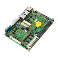
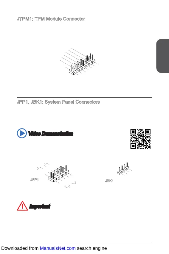
JTPM1: TPM Module Connector
This connector connects to a TPM (Trusted Platform Module). Please refer to the
TPM security platform manual for more details and usages.
10.No Pin
14.Ground
8.5V Power
12.Ground
6.Serial IRQ
4.3.3V Power
2.3V Standby power
1.LPC Clock
3.LPC Reset
5.LPC address & data pin0
7.LPC address & data pin1
9.LPC address & data pin2
11.LPC address & data p
13.LPC Frame
JFP1, JBK1: System Panel Connectors
These connectors connect to the front panel switches and LEDs. The JFP1
connector is compliant with the Intel
®
Front Panel I/O Connectivity Design Guide.
When installing the front panel connectors, please use the optional M-Connector to
simplify installation. Plug all the wires from the computer case into the M-Connector
and then plug the M-Connector into the motherboard.
Video Demonstration
Watch the video to learn how to Install front panel connectors.
http://youtu.be/DPELIdVNZUI
3 .BUZ-
4 .Speaker+
1 .
S peaker-
2 .
B UZ+
1.+
3.-
10.No Pin
5.-
Reset S
HDD LE
ower Switch
ower LED
7.+
9.Reserved
8.-
6.+
4.-
2.+
JFP1
JBK1
Important
On the connectors coming from the case, pins marked by small triangles are
positive wires. Please use the diagrams above and the writing on the optional M-
Connectors to determine correct connector orientation and placement.
The majority of the computer case’s front panel connectors will primarily be
plugged into JFP1.
Downloaded from ManualsNet.com search engine
 Loading...