1
Touch Screen
The user-friendly touch screen enables eective operation and control of the
system on the user’s end.
2
Antenna Connector (Optional)
This connector allows you to connect an external antenna for wireless LAN.
Users may nd one antenna connector on the bottom I/O panel and two on the
left and right sides of the system.
3
DC Power Jack
Power supplied through this jack supplies power to the system.
4
Power Supply Switch
Press the switch to turn the power supply on or o.
5
AT/ATX Switch
Use this switch to select between AT and ATX power modes.
6
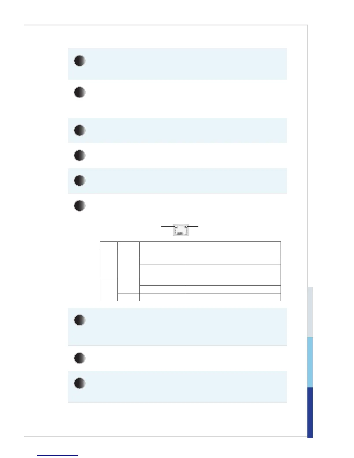
RJ45 LAN Jack
The standard RJ-45 LAN jack is provided for connection to the Local Area
Network (LAN). You can connect a network cable to it.
Yellow Green/ Orange
LED Color LED State Condition
Left Yellow Off LAN link is not established.
On (steady state) LAN link is established.
On (blinking) The computer is communicating with another
computer on the LAN.
Right Green Off 10 Mbit/sec data rate is selected.
On 100 Mbit/sec data rate is selected.
Orange On 1000 Mbit/sec data rate is selected.
7
RS232/422/485 Serial Port: COM1
The serial port is a 16550A high speed communications port that sends/
receives 16 bytes FIFOs. It supports barcode scanners, barcode printers, bill
printers, credit card machine, etc. The power voltage is selectable by BIOS.
8
VGA Port
The DB15-pin female connector is provided for VGA-interface devices.
9
USB 3.0 Port
The USB 3.0 port is backward-compatible with USB 2.0 devices and supports
data transfer rate up to 5 Gbit/s (SuperSpeed).