En-17
Englsh
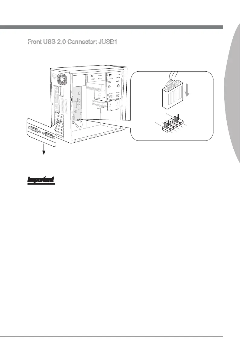
Front USB 2.0 Connector: JUSB1
Ths connector, complant wth Intel
®
I/O Connectvty Desgn Gude, s deal for con-
nectng hgh-speed USB nterface perpherals such as USB HDD, dgtal cameras, MP3
players, prnters, modems and the lke.
1.VC
C
3.USB 0
-
10.NC
5.USB 0
+
7
.Grou n d
9.No
Pin
8
.Grou n d
6.USB 1
+
4.USB 1
-
2.VC
C
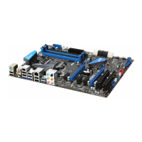
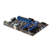
* The MB layout n ths gure s for reference only.
USB Bracket (optonal)
Important
Note that the pns of VCC and GND must be connected correctly to avod possble
damage.
The JUSB1 (red mark) supports MSI newly Super-Charger technology. Wth Super-
Charger technology, the JUSB1 can only provde chargng functon n S0 (power-on),
S3 (sleep mode) & S5 (shut-down) states. However, the synchronzng data lnk wll
be dsabled. In ths case, the system can not be awaked through the JUSB1.
For Super-Charger n S3 (sleep mode)/ S5 (shut-down), we suggest you to connect
only one devce for stable chargng.
Super-Charger technology would be avalable on specc models, please refer to MSI
webste for model support lst.
•
•
•
•
 Loading...