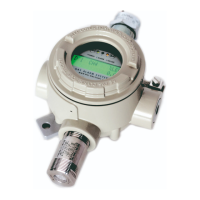
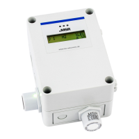
The PolyXeta®2 Gas Detector Series is a fixed gas detector designed for continuous monitoring of gas-air mixtures under atmospheric conditions, specifically for Freon gases and refrigerants in hazardous areas classified as Zone 1 and Zone 2. The device consists of a sensor head and an I/O unit, with an optional display unit for local indication of measurement values and status.
Function Description
The PolyXeta®2 detector utilizes semiconductor gas sensors (metal oxide sensors) to detect the presence of Freon gases and refrigerants. These sensors operate by changing their electrical conductivity upon contact with the target gas. The reaction is reversible, and the sensors are suitable for a wide range of reactive gases. The signal, which is logarithmic to the gas concentration, is evaluated by a measuring amplifier and converted into a linear 4-20 mA output signal.
The sensor head, housed in a flameproof stainless-steel enclosure (Ex d), integrates the gas sensor, evaluation electronics, calibration, and diagnostic functions. All sensor-specific data is stored within the sensor head itself. This design allows for easy replacement of the sensor head with a pre-calibrated or new one at the end of its calibration period or lifetime.
The I/O unit, which includes the operating power supply, communicates with the sensor head via an internal local bus. It monitors communication and translates the sensor head's measured value into a 4-20 mA signal. Gas concentration, relevant data, and status messages are available on a central bus. An alarm relay activates when a predefined alarm threshold is exceeded. In the event of a fault, a fault relay is triggered, and the analog output shifts to a fault state, with the fault message transmitted via the central bus.
The device supports various operating modes:
- Restart (Diagnostic and Warm-up Stage): Upon power-up or internal reset, the detector undergoes a diagnostic and warm-up phase, during which it performs self-tests and stabilizes the sensor.
- Measuring Mode: This is the normal operating mode where the detector continuously monitors gas concentrations. Alarm acknowledgements can be performed in this mode.
- Special Mode: An operator-triggered mode for specific functions, potentially involving maintenance or advanced diagnostics.
- Faults: The device indicates various fault conditions, such as sensor element defects, processor failures, or communication errors, through status LEDs, analog output changes, and relay activations.
Important Technical Specifications
- Power Supply: 20-28 V DC (reverse polarity protected) or 24 V AC ± 10% (21.6-26.4 V AC).
- Maximum Supply Current: 130 mA (for 24 V DC).
- Power Consumption (max.): 3.3 W.
- Analog Output Signal: 4-20 mA, proportional, overload and short-circuit protected, max. load 500 Ohm.
- Relays:
- Fault message relay (SPNC): Max. 30 V AC/DC, 1 A.
- Alarm relay (SPDT): Min. 12 V AC/DC, 0.1A.
- Temperature Range:
- Without display: -25 °C to +60 °C (-13 °F to 140 °F).
- With display: -20 °C to +60 °C (-4 °F to 140 °F).
- Humidity Range: 20-90% RH (non-condensing).
- Pressure Range: 800 to 1200 mbar (80 to 120 kPa).
- Storage Conditions: -10 °C to +40 °C (14 °F to 104 °F), 40-70% RH (non-condensing), 800 to 1200 mbar (80 to 120 kPa), max. 6 months storage time.
- Serial Interface: 19200 Baud (Transceiver).
- Housing (Standard): Aluminum die-cast / RAL 7032, epoxy coating. Dimensions: 125 x 162 x 83 mm (4.92 x 6.38 x 3.27 in.). Weight: Approx. 1.3 kg (2.87 lb.).
- Protection Class: IP66 to IP68 (depending on cable glands).
- Sensor Head: Stainless steel 1.44004 / natural. Dimensions: 30 x 56 mm (1.18 x 2.20 in.). Weight: Approx. 0.15 kg (0.33 lb.).
- Sensor Head Protection Class: IP64, with optional splash guard IP65.
- Sinter Element: Stainless steel 1.4404, min. density 4.15 g/cm³ (acc. to ISO 2738), 18 x 6 mm dimensions, max. pore size 125 μm.
- Approvals:
- PX2-1 series: ATEX Directive 2014/34/EU (II 2G Ex db IIC T4 Gb) and IECEx (Ex db IIC T4 Gb).
- PX2-2 series: ATEX Declaration of Conformity for Zone 2 (II 3G Ex nA IIC T4 Gb).
- Warranty: 1 year on sensor (unless poisoned or overloaded), 2 years on device.
Usage Features
- Installation: The device is designed for wall mounting with the sensor head pointing downwards to prevent dust and liquids from clogging the gas inlet. Mounting height depends on the relative gas density of the monitored gas. Installation must be carried out under gas-free conditions, and the housing should not be drilled.
- Site Selection: Careful consideration of ambient conditions is crucial for accurate measurements. External heat sources, strong air currents (>6 m/s, requiring a wind shield), and areas with significant vibration or temperature variations should be avoided. Adequate space for maintenance and calibration must be provided around the sensor.
- Display (Optional): An optional display unit with status LEDs (Green for operation, Yellow for failure/warm-up/special mode, Red for alarm) provides local indication. The display backlight changes from green to red during an alarm.
- Operation: Contactless menu operation is possible from the outside using a magnetic pen, allowing access to device parameters and measured values. Parameter changes are password-protected.
- Deadband: A deadband function can be activated to suppress unwanted noise around the zero point, with a range of up to ±5% of the measuring range. This function automatically switches off when calibration mode is opened.
- Gas Detection: The detector is designed to monitor ambient air for Freon refrigerant gases based on the built-in sensor head.
- Environmental Considerations: High concentrations of certain compounds (polymerizing substances, catalytic poisons, organic solvents) can contaminate or destroy the sensor, requiring more frequent calibration. Dust deposits can extend response time, necessitating regular cleaning and functional tests. Painting near the device requires sealing the gas inlet to prevent damage from paint deposits or solvent emissions.
Maintenance Features
- Regular Maintenance: Maintenance is mandatory to ensure safety and proper functioning. It must be performed by appropriately qualified personnel.
- Visual Inspection: Includes checking for mechanical damage, dust/dirt/moisture deposits on the gas inlet, proper locking of the cover screw, and verifying operational and status messages on the display. A report of the inspection should be kept.
- Functional Control / Calibration and Adjustment:
- Zero-point Check: Apply zero gas; if the measured value is outside the permissible range, a zero calibration is required.
- Sensor Sensitivity Check: Apply test gas; if the measured value is outside the permissible range, a gain calibration is required.
- Response Time Check: Apply test gas and check the time until the alarm is triggered. If it exceeds the specified time, the sensor head must be replaced.
- Calibration Procedure: Involves screwing a calibration adapter onto the sensor head, entering calibration mode, waiting for warm-up, and performing zero and gain calibrations using specific test gases and flow rates. Extended calibration procedures are available for situations where the set test gas concentration is not reached in the display.
- Sensor Head Exchange: The sensor head can be easily replaced. This involves disconnecting the sensor head, unscrewing it, and installing a new or pre-calibrated sensor head. Recommissioning and functional tests are required after replacement.
- Repairs: Only original spare parts from MSR-Electronic should be used. Repairs or unauthorized modifications will void the warranty and certificates. Repair work must be carried out by trained and authorized service partners. After any repair, a functional and system check is necessary before restarting the device.
- Documentation: Successful calibration must be documented with a protocol, and a label indicating the next calibration date should be attached to the detector.