ASSEMBLY & INSTALLATION
6
Required Tools
• 7/16” Socket Wrench (2)
• 1/2” Socket Wrench
Mounting LT-5 Bracket Assembly
NOTE: References to left, right, front and rear of the tractor are from the operator’s position,
unless otherwise stated.
• Before assembly, place the tractor on a firm, level surface, disengage the
PTO, stop the tractor engine and set the parking brake.
• For convenience, pivot seat forward and leave it in that position until the
grass collector is fully mounted and assembled.
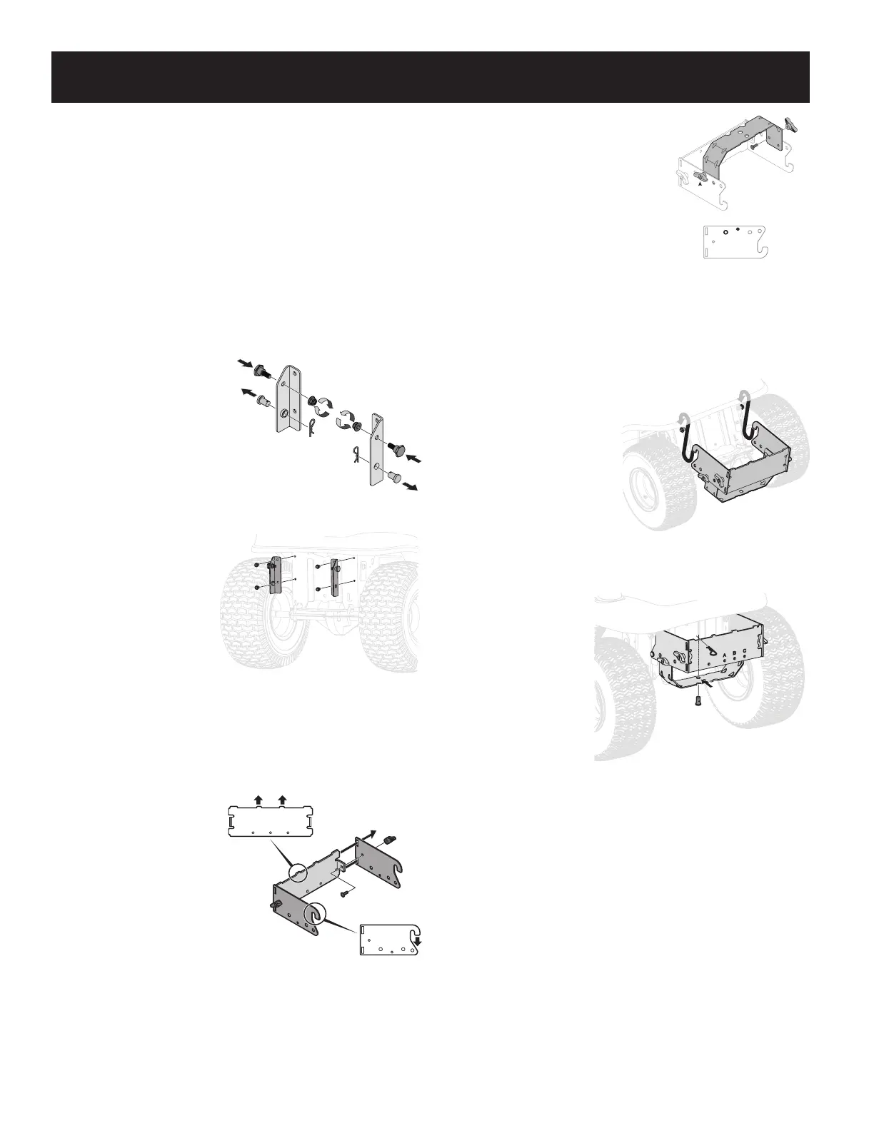
To install LT-5 brackets, follow these steps:
1. If not already installed by the
factory, install a shoulder bolt
from the hardware pack on
each bracket, securing them
with flange lock nuts also
included in the LT-5 Bracket
Assembly (689-00086A)
hardware pack. Refer to
Figure 2.
2. If already installed in
the brackets, remove
the clevis pins and
clips, retain for later
instructions. Refer to
Figure 2.
3. Mount the mounting
brackets to your tractor
using four self-tapping
hex screws included with
your kit. See Figure 3.
Assemble Mounting Brackets
To assemble the universal mounting assembly, locate the rider hitch bracket
assembly (689-00304A) and the universal support bracket (783-08129) and follow
these steps:
1. Attach the two hitch side
brackets to the rear support
bracket (rider hitch bracket
assembly 689-00304A) using
two carriage bolts (710-0276)
and wing knobs (720-04122)
from hardware pack 689-
02364. See Figure 4.
NOTE: Hooks on side brackets
should point downwards and
tabs on rear support bracket
point upwards as shown in
Figure 4.
2. Flip over assembly and mount hitch
support bracket to universal support
bracket (783-08129) using two carriage
bolts (710-0276) and wing knobs
(720-04122) from hardware pack 689-
02364, as shown in Figure 5.
NOTE: It might be easier during the
mounting stage to leave this hardware
only finger tight to facilitate lining up the
hitch hole for the clevis pin. You will be
instructed to tighten this hardware later in
this manual.
Mount Assembly on Tractor
Install mounting assembly on tractor as follows:
1. Place hooked ends of
mounting assembly over
shoulder bolts on LT-5
brackets previously installed
on back of tractor frame, as
shown in Figure 6, and line
up hitch support bracket
center hole with hole on the
tractor’s hitch.
2. Replace clevis pins and cotter
pins removed in Mounting
LT-5 Bracket Assembly
section. See Figure 2.
3. Install the clevis
pin (711-0309A)
from hardware pack
689-02364 into the
tractor’s hitch and
secure with cotter
pin (714-0117). See
Figure 7.
NOTE: The clevis pin can
be fed down through
the hitch plate and
secured underneath
with the cotter pin, or it may be easier to feed the clevis pin up through the hitch
plate hole and secure with the cotter pin on the topside. Insert the cotter pin into the
top hole, closest to the head of the pin. You may need to push up on the pin to make
the hole accessible.
IMPORTANT! If you decided to leave the hitch support only finger tight during the
assembly process, tighten all of the hardware securely at this time.
Figure 2
Figure 3
Figure 4
Side View
Figure 5
Figure 6
Align hole on bracket
with hole on tractor
Figure 7


 To Next Page
 Loading...