WARNING
'Excessive pressure
when seating beads
_maycausetire/rim
_assembly to burst
with force sufficientto
cause serious injury.
Referto sidewall of
,tire for recommended
;pressure.
6. Installpumpcouplinghalfand keyon pumpshaft.
Rotatecouplinghalfuntilsetscrewfacesopeningin
shield.Donottightensetscrew.
7. Installnylon"spider"onto enginecouplinghalf.
8. Alignpumpcouplinghalfwith nylon"spider"by rotat-
ingengineusingstarterhandle.Slidecouplinghalf
intoplacewhileguidingthreemountingboltsthrough
holesin pumpsupportbracket.
9. Securewithnuts removedearlier.
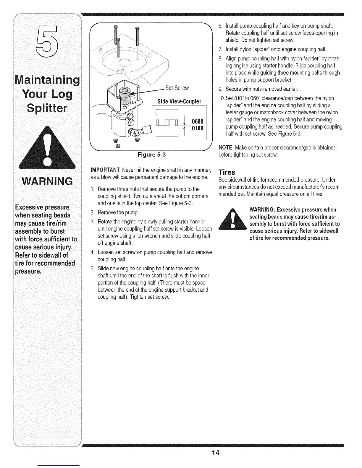
10.Set.010"to.060"clearance/gapbetweenthenylon
"spider"andthe enginecouplinghalfby slidinga
feelergaugeor matchbookcoverbetweenthenylon
"spider"andthe enginecouplinghalfand moving
pumpcouplinghalfasneeded.Securepumpcoupling
halfwith setscrew.SeeFigure5-3.
Figure 5=3
NOTE:Makecertainproperclearance/gapisobtained
beforetighteningsetscrew.
IMPORTANT:Neverhittheengineshaftinanymanner,
asa blowwill causepermanentdamagetotheengine.
1. Removethreenutsthat securethepumptothe
couplingshield.Twonutsareatthebottomcorners
andoneisin thetopcenter.SeeFigure5-3.
2. Removethepump.
3. Rotatetheenginebyslowlypullingstarterhandle
untilenginecouplinghalfset screwisvisible.Loosen
setscrewusingallenwrenchand slidecouplinghalf
offengineshaft.
4. Loosenset screwon pumpcouplinghalfand remove
couplinghalf.
5. Slidenewenginecouplinghalfontotheengine
shaftuntiltheendofthe shaftisflushwiththeinner
portionofthecouplinghalf.(Theremustbespace
betweentheendoftheenginesupportbracketand
couplinghalf).Tightensetscrew.
Tires
Seesidewalloftireforrecommendedpressure.Under
anycircumstancesdo notexceedmanufacturer'srecom-
mendedpsi. Maintainequalpressureon alltires.
,_l_k,, WARNING:Excessivepressurewhen
seatingbeadsmay causetire/rim as-
sembly to burst with force sufficient to
cause serious injury.Referto sidewall
of tire for recommendedpressure.
14