24
After replacing the drive belts, adjust the drive
pedal on your tractor as follows:
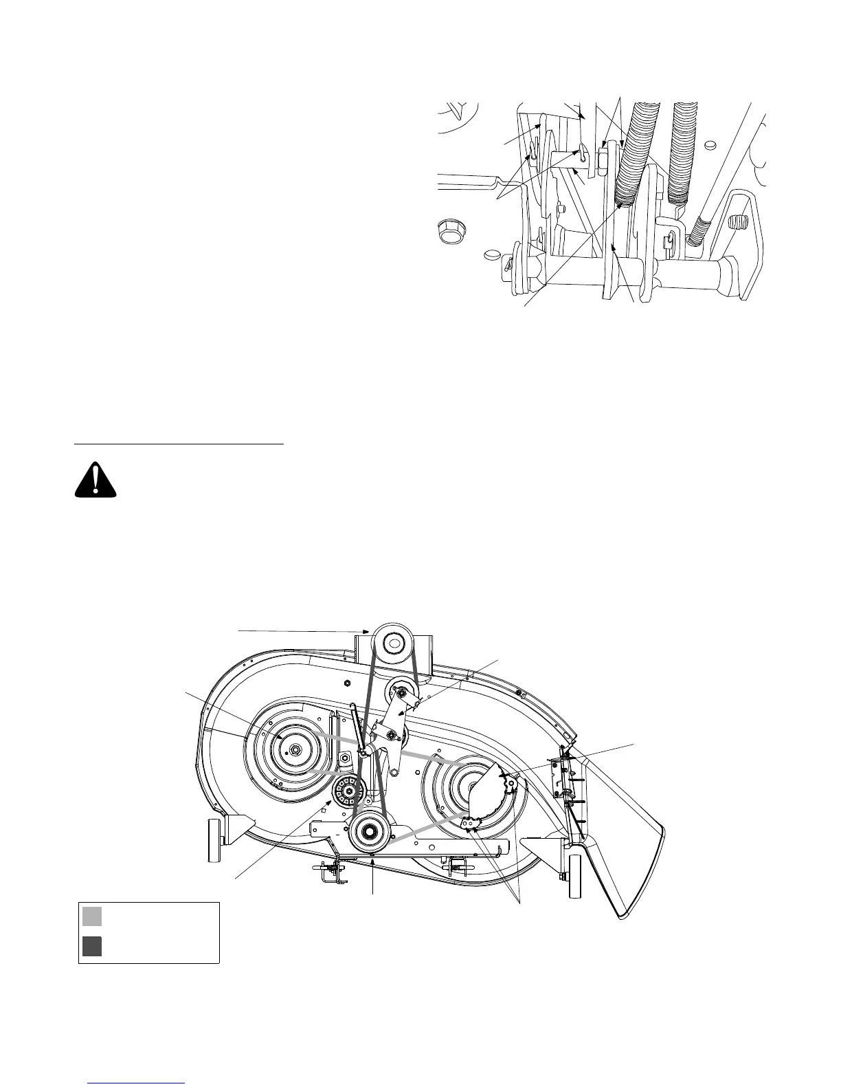
1. Locate the speed control assembly on the
underside of the steering support bracket. See
Figure 17.
2. Remove both hairpin clips from the pin which is
fastened to the speed control assembly (be careful
not to lose the small flat washers found on the pin).
See Figure 17.
3. Remove the drive pedal return spring.
4. Using two 9/16" wrenches, remove the pin from the
speed control assembly. See Figure 17.
5. Thread the idler adjustment rod inward or outward
to lengthen or shorten the travel of the double-idler
bracket until proper adjustment is achieved.
6. Reassemble by following the above steps in
reverse order.
Changing the Deck Belt(s)
IMPORTANT:
The V-belts on your tractor are specially designed to engage and disengage safely. A substitute (non-
OEM) V-belt can be dangerous by not disengaging completely. For a proper working machine, use factory
approved belts.
WARNING: Shut tractor engine off, remove ignition key, disconnect the spark plug wire(s) and ground
against the engine before proceeding with job.
Speed Control
Assembly
Hairpin
Clips
Idler
Adj. Rod
Pin
AutoDrive
™
Pedal
Return Spring
Place Wrenches Here
Neutral
Return
Bracket
Figure 17
Engine Pulley
PTO Idler Bracket
Left Hand Pulley
Right Hand Pulley
(beneath belt guard)
Center Pulley
Deck Idler Pulley
Self-Tapping Screws
(mounted on tractor)
42-inch Decks
Deck Belt (Bottom)
PTO Belt (Top)
(or Electric PTO Clutch)
Figure 18