15
Simulated Encoder Signals
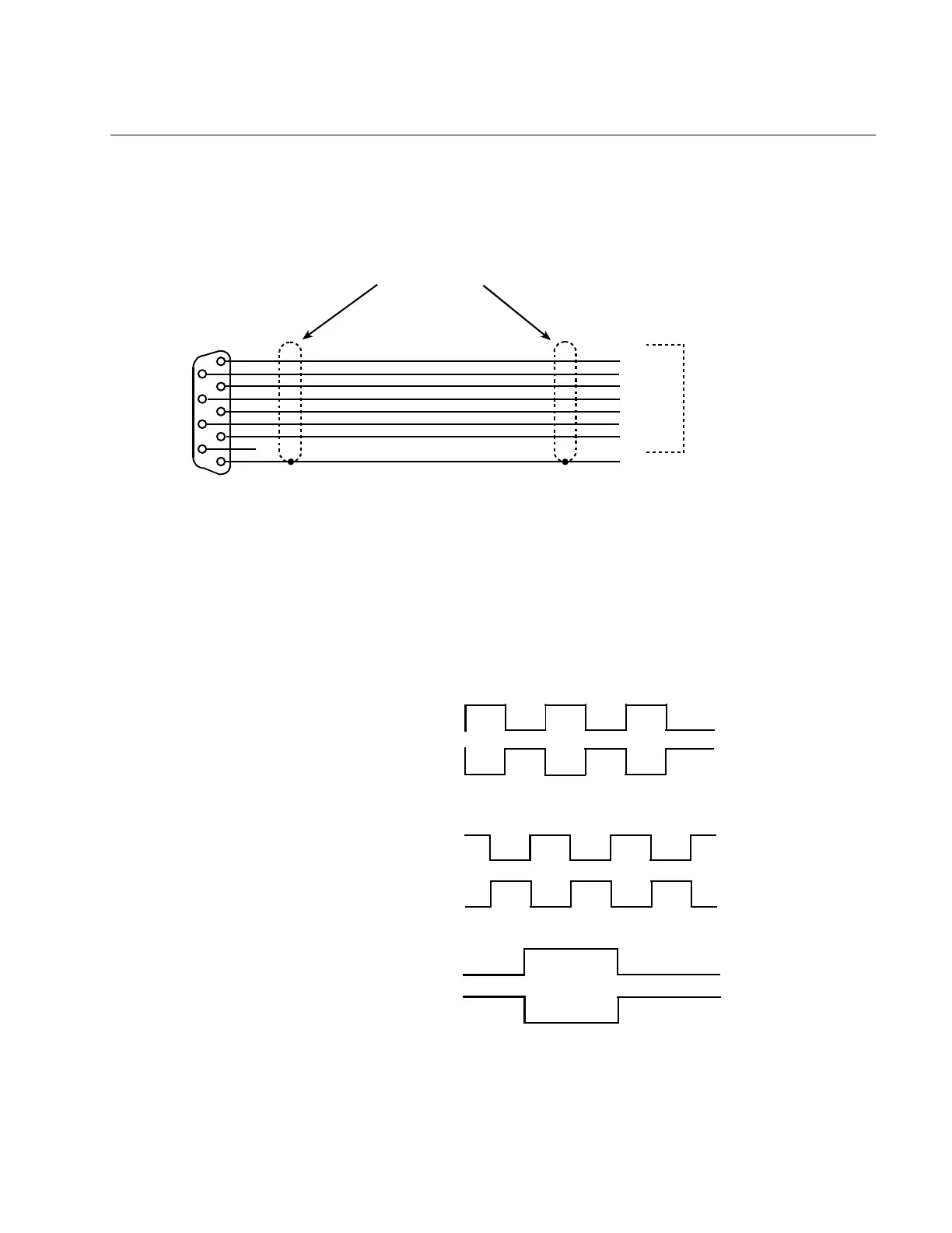
For external counting or position control, 9-pin D type female connector that has TTL
complimentary outputs is provided. This simulates quadrature encoder channel A and
channel B signals. A differential mark signal is also available.
1
6
2
7
3
8
4
9
5
A\
A
B
B\
M
M\
GND
EXTERNAL CONTROLLER
SIGNALS AND GND
ENCODER
SIMULATION CONNECTOR
P1
COMMENTS:
1) THE AMPLIFIER OUTPUTS ARE RS422 DIFFERENTIAL LINE DRIVER COMPATIBLE
2) THEY SHOULD BE CONNECTED TO COMPATIBLE DIFFERENTIAL RECEIVERS
3) THE BEST SHIELDING APPROACH WOULD BE TO CONNECT THE SHIELD AT THE AMPLIFIER END ONLY
4) ALL SIX WIRES AND A GND CONNECTION SHOULD BE CONNECTED AT THE CONTROLLER END
100% SHIELD
(FOIL AND BRAID)
The phase relationship of channels A, B, and M are as follows for CW rotation:
1 A\
6 A
2 B
7 B\
3 M
8 M\
The marker pulse is about .5 degrees in width. The above illustration is for 1024 line
condition(default).
The above signals are TTL complimentary outputs from a DS26LS31 differential driver.
The logic 0 is typically between 0 and .5 volts and logic 1 is typically between 3.3 and 4
volts.
 Loading...