17
I/O Wiring and Descriptions
The amplifier has four inputs and one output. These inputs and output are designed to
interface to a 24 volt logic system. The amplifier is shipped so that the operation of the
inputs are as follows.
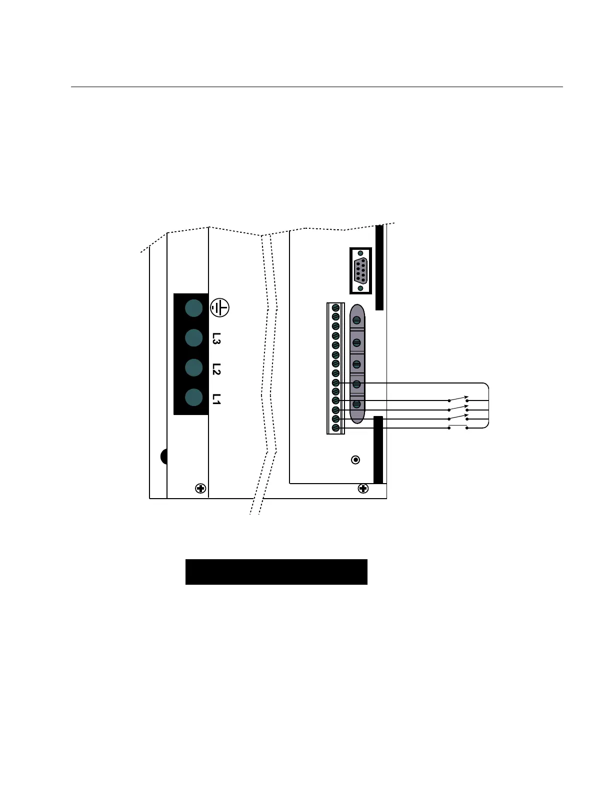
With no wires connected to RESET, + LIMIT, - LIMIT, or VEL/TORQUE, the amplifier is
enabled and normal operation will occur in a velocity mode. The inputs are activated by
connecting them with a switch closure to any of the provided GND terminals.
I/O Wiring Example
LEAD
SIG
RESP
CUR
BAL
RESET
I/O
GND
-AUX
+AUX
GND
-COM
+COM
CUR
VEL
GND
FLT
V/T
-LIM
+LIM
RES
ENCODER
The actual decision as to open or closed switches occurs at a voltage level between 5-8
volts DC. Less than 5 volts is active; greater than 8 volts is inactive.
NOTE
The V/T is an input that determines the
amplifier mode, Velocity/Torque mode.
When the switch is open, the Velocity
mode is selected. When the switch is
closed, the Torque mode is selected.
As the polarity of the inputs may vary depending on the application, a DIP switch is
provided to allow for an inversion of the function.
 Loading...