19
Analog Inputs, Outputs and Adjustments
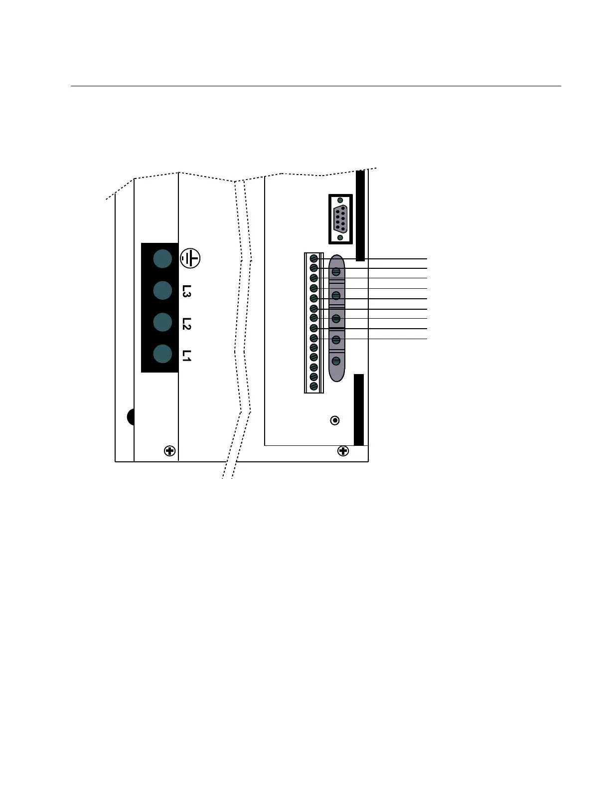
Inputs
There are two analog input channels; one for command and one for auxiliary. Both of
these channels are differential inputs and both are summed with a TAC feedback
differential amplifier that controls velocity.
LEAD
SIG
RESP
CUR
BAL
RESET
I/O
GND
-AUX
+AUX
GND
-COM
+COM
CUR
VEL
GND
FLT
V/T
-LIM
+LIM
RES
ENCODER
}
}
ANALOG INPUT
WIRING EXAMPLE
GND
– AUX SIGNAL
+ AUX SIGNAL
GND
– COMMAND SIGNAL
+ COMMAND SIGNAL
CURRENT
TAC
GND
Normal operation of the command signal is to apply a + voltage (pin #9) with respect to
GND (pin #11) and get clockwise rotation of the shaft. ±10 volts is then used to control
velocity, and the SIG pot is used for velocity adjustments. If the + COMMAND voltage is
applied to the - COMMAND signal input, then an opposite shaft rotation occurs.
The operation of the AUXILIARY ± inputs is the same as the COMMAND inputs. The
normal purpose of the AUXILIARY inputs is to provide a second summing voltage to
compensate/modify normal COMMAND voltage.
If the input for VEL/TORQUE is active and a torque mode is chosen then voltages applied
to the COMMAND ± inputs control motor current. The SIG pot can now be used to adjust
the current. Normal operation in this mode assumes that 10 volts represents peak current
and 5 volts represents the continuous current rating of the amplifier.
The current limit of the amplifier can be adjusted with the CUR pot from 0 (full CCW) to
100% (peak full CW). It is a good idea during start-up to adjust the CUR pot to its full
CCW position and increase it slowly CW to assure normal operation.
 Loading...