20
During start-up the BAL adjustment can be used to reduce/stop any low speed CW/CCW
drift caused by imbalance between the external command voltage and the amplifier.
Once connected to loads, the crispness of motion (step response) and stability can be
optimized with the RESP and LEAD pots. Full CW is maximum response and full CCW is
minimum LEAD.
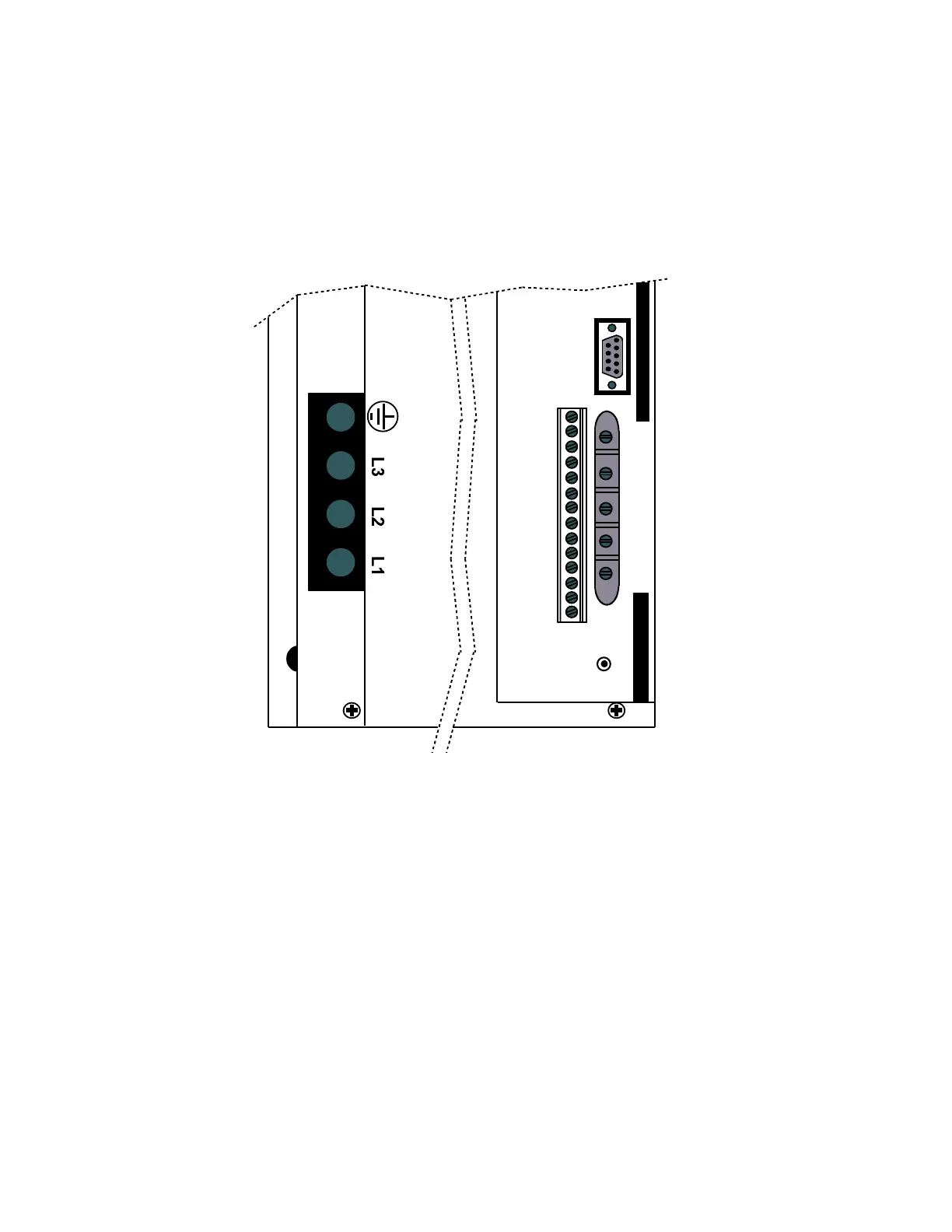
The location of these adjustments is next to the I/O wiring.
FEEDBACK AND I/O CONTROL ASSEMBLY
LEAD
SIG
RESP
CUR
BAL
RESET
I/O
GND
-AUX
+AUX
GND
-COM
+COM
CUR
VEL
GND
FLT
V/T
-LIM
+LIM
RES
ENCODER
Outputs
Two diagnostic outputs are the dc voltage proportional to velocity and the dc output
proportional to current/torque. The nominal TAC gradient is determined by DIP switches
in a range of ±10 volts. The current gradient is 10 volts equal peak.
 Loading...