25
Lead/Lag Compensation
SW1 is provided as a means to alter the amplifier's lead/lag network. Switches 1-4 can be
switched ON to allow for forward compensation of the TAC signal in the summing node of
the differential amplifier used for the velocity loop. This signal had the effect of damping
the loop, and is an effective method to control large inertia loads. The addition of lead
compensation may alter the lag compensation network and the range of the response
adjustment. SW1 switches 5-8 allow for changing the RC network associated with the lag
network which determines the range of the response adjustment. It is an empirical
process to determine the best value, but the process is based on a short procedure.
1. Add lead compensation in the smallest increment.
2. Make a small alteration of the lag resistor then capacitor.
3. Check for adequate RESP adjustment range.
4. Repeat sequence if range is not adequate.
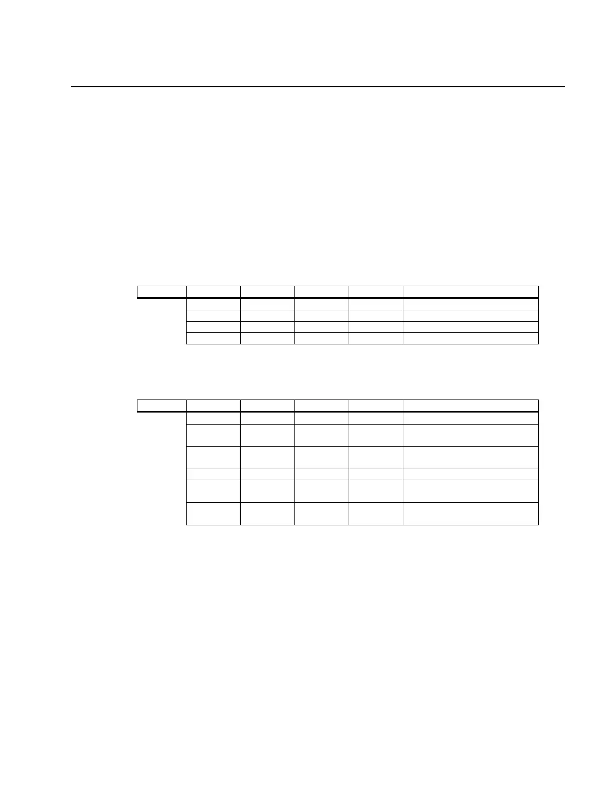
SW1 switches 1-4 allow the addition of a lead capacitor. Each switch represents a
different value that can be used in parallel with any combination of the four switches.
SW1 1 2 3 4 Lead Capacitor
ON OFF OFF OFF .047M
OFF ON OFF OFF .1M
OFF OFF ON OFF .22M
OFF OFF OFF ON .47M
SW1 switches 5-8 allow for alteration of the lag resistor and lag capacitor. Multiple
combinations can be used for different RC network values.
SW1 5 6 7 8 Lag Alteration
OFF OFF — — lag capacitor is .047M
ON OFF — — add .47M in parallel to the
.047M
OFF ON — — add .22M in parallel to the
.047M
— — OFF OFF lag resistor is 200K
— — ON OFF add 30k in parallel to the
200K
— — OFF ON add 200K in parallel to the
200K
 Loading...