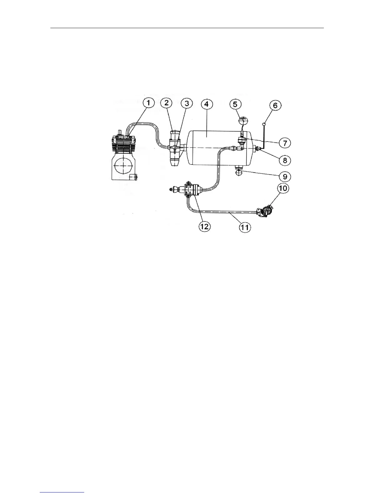
Pneumatic system of trailer brake control
Single-line pneumatic actuator
1 – compressor; 2 – pressure regulator; 3 – air intake valve; 4 – tank; 5 – pressure indi-
cator; 6 – emergency pressure pilot lamp; 7 – pressure transducer; 8 – emergency
pressure sensor; 9 – condensate removal valve; 10 – connecting head; 11 – control
line; 12 – brake valve.
The tractor is equipped with the pneu-
matic system controlling the brakes of
the trailers and other agricultural ma-
chines equipped with pneumatic brake
actuator.
The pneumatic system is also used for
inflating the tyres and other purposes,
when compressed air power is required.
The pneumatic system is also used for
inflating the tyres and other purposes,
when compressed air power is required.
Air is taken to the system from the en-
gine intake manifold. Air is compressed
in the compressor (1) and supplied to
tank (4) via pressure regulator (2) main-
taining the required pressure in the tank.
Compressed air is supplied from the
tank via pipeline to the brake valve (12).
From the brake valve air is passed via
control line (11) to the connecting head
(10) and then to the pneumatic system
of the trailer. The air intake valve (3),
which used for inflating the tyres and
other purposes, is installed in the pres-
sure regulator. To monitor air pressure
in the system, there is a pressure trans-
ducer (7) and the emergency pressure
drop sensor (8) and on the dashboard –
pressure indicator (5) and red pilot lamp
(6). To remove condensate from the
tank, the valve (9) is provided.
The brakes of the trailers and agricultur-
al machines are controlled in two
modes: direct and automatic.
The direct control of the brakes is exer-
cised at the cost of the pressure drop in
the connecting line when braking the
tractor to zero.
The automatic brake control is exercised
by at the cost of the pressure drop to ze-
ro in the trailer connecting line in case of
its disconnection (detachment) from the
tractor. Here the valve in the connecting
head of the tractor is automatically shut