1. General
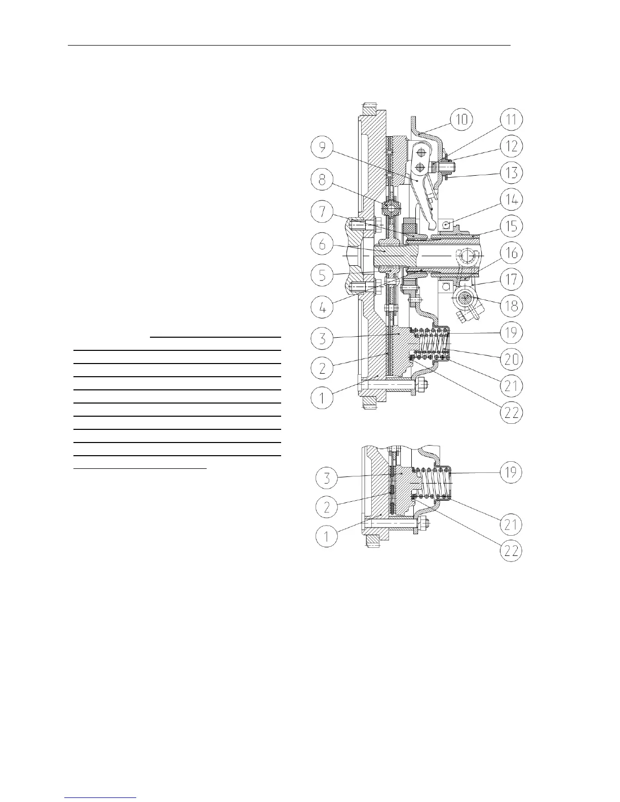
A dry single-plate spring-loaded clutch is
mounted on the engine flywheel (1) (see
Fig. а).
The driving part of the clutch consists of
the flywheel (1) and pressure plate (3).
The driven part of the clutch includes the
driven plate (2) with the torsional vibra-
tion damper (8) mounted on the power
shaft (6). The necessary force for press-
ing the friction surfaces of the driving
and driven parts is provided by the nine
main springs (21) and six additional
springs (20), if the clutch is equipped
with a driven plate 2 with ceramic-metal
segments (Fig. b), no additional springs
(20) are mounted in this case.
ATTENTION: To avoid the premature
failure of the driven plate and parts of
the transmission, follow the guidelines of
this Manual: in case of installation of a
driven plate with asbestos-free linings
(Fig.а), the clutch plates are fitted with
nine main springs 21 and six additional
springs 20; in case of installation of a
driven plate with ceramic-metal seg-
ments, the clutch plates are fitted with
nine main springs 21 only.
The elastic components are placed be-
tween the floating bushing (7) connected
with the PTO drive shaft (4) and the
backing plate (10).
The clutch is engaged and disengaged
by means of the shifter (16) with the re-
lease bearing (14) moving over the
bracket (15). The shifter fork (17) with
the roller (18) is connected with the
clutch pedal by means of a rod.
The release bearing (14) is lubricated
through a pressure lubricator screwed in-
to the shifter journal.
a)
b)
1 – flywheel; 2 – driven plate; 3 – pres-
sure plate; 4 – PTO drive shaft; 5 – hub; 6
– power shaft; 7 – floating bushing; 8 –
torsional vibration damper; 9 – clutch lev-
er; 10 – backing plate; 11 – fork; 12 – nut;
13 – locking spring; 14 – bearing; 15 –
shifter bracket; 16 – shifter; 17 – disen-
gagement fork; 18 – control roller;
19 – sleeve; 20 – pressure spring;
21 – pressure spring; 22 – insulating
w a sher.
Clutch