Controls and Instrumentation
Indicator of the fuel level in the tank (4)
with orange control lamp of reserve level. It op-
erates with the fuel level sensor (BN1).
The instrument has the points: 0-1/4-1/2-3/4-
1.
Do not allow consuming the fuel to empty
tank (instrument pointer is at orange zone).
Voltage indicator (5) with the red control
lamp red of additional SB charging.
It displays the SB voltage, when the engine
is running and the starter switch key is in the
“I” position. When the engine is running, it
indicates the voltage at the generator termi-
nals.
The reading values are given in Table 14 be-
low.
Table 14
Power supply system state
when the engine
is running
when the engine
is not running
No charging of
SB (low charg-
ing voltage)
White hairline in
yellow zone
The rated emf
of the SB is12.7
V
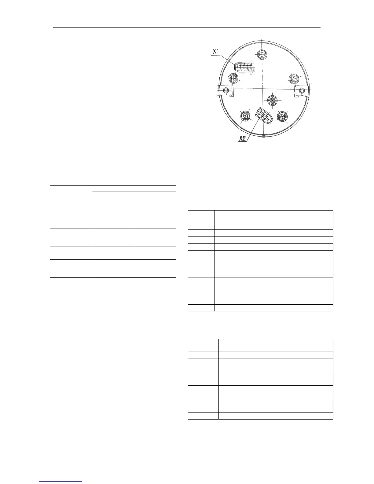
1.15. Connection the combination meter
To integrate the combination meter to the in-
strumentation system, the rear panel is pro-
vided with two blocks Х1 and Х2 (Fig. 8).
The purpose of the contacts of the blocks of
the combination meter is shown in Tables
15, 16.
Fig. 8. Blocks for connecting the combination meter (rear
view):
Х1 – 9-contact block;
Х2 – 7-contact block.
Block Х 1
Table 15
To the instrument backlight switch
To the “–” terminal of the battery
Monitoring the storage battery charging
To the sensor of the oil pressure in the en-
gine (ВР1)
To the sensor of the emergency tempera-
ture of the engine cooling fluid (SК1)
To the sensor of the emergency oil pressure
in the engine (SP2)
To the sensor of the cooling fluid tempera-
ture (BK1)
To the “+” SB terminal (12 V)
To the fuel level sensor (BN1)
To the gearbox oil pressure sensor (not
used)
To the sensor of emergency drop of the
air pressure (SP4)
To the sensor of the reserve fuel level
(BN1)
To the sensor of the air pressure (ВР2)