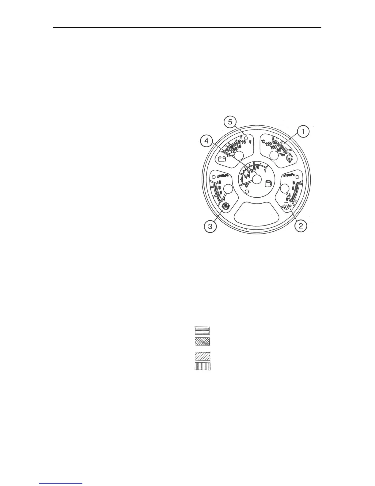
1.14. Combination meter (Fig. 7)
The combination meter includes the five
gauges (1, 2, 3, 4, 5) monitoring the various
parameters of the tractor. All the gauges are
provided with emergency control lamps. The
gauges (1, 2, 3, 5) have the red control lamps,
and the indicator (4) – the yellow control lamp.
To switch on the combination meter, turn the
key of the starter and instrumentation switch
(SA6) to the “I” position. In this case, the
pointer of the oil pressure indicator (2) and
temperature indicator (1) shall move to the ze-
ro marks of the scale and the pointers of the
air pressure indicator (3), fuel level indicator
(4) and voltage indicator (5) shall be set to the
positions corresponding to the actual positions
of the parameter monitored.
The electrical circuit of the instruments is pro-
tected by the fuse “2” in the unit (F2).
Engine cooling fluid temperature indicator
(1) with the emergency temperature control
lamp (red). It operates with the temperature
sensor (BK1). The indicator scale has three
zones:
– operating – 80…100°C – green;
– non-operating – 40…80°C – yellow;
100…120°C – red.
Engine oil pressure indicator (2)
with emergency pressure drop control lamp
(red). It operates with the pressure sensor
(BP1).
The indicator scale has three zones:
– operating – 100…500 kPa – green;
– non-operating – 0…100 kPa and
500…600 kPa – red.
When starting the cold engine, the pressure of
up to 600 kPa is possible.
Indicator of the air pressure in the pneumatic
system (3) with the red emergency pressure
control lamp. It operates with the air pressure
sensor (ВР2).
The indicator scale has three zones:
- operating – 500…800 kPa – green;
- non-operating – 0…500 kPa and
800…1000 kPa – red.
Fig. 7. Combination meter:
1 – engine cooling fluid temperature indicator;
2 – indicator of the engine oil pressure;
3 – indicator of the air pressure in the pneu-
matic system;
4 – indicator of the fuel level in the tank;
5 – indicator of voltage of the storage battery
or alternator.
Scale zones marked by hatching:
– red
– yellow
– green
– orange