1.13. Setting and Adjustment of the speed
sensors (BV1, BV2) (Fig. 6)
The speed sensors (2) are fastened by means
of the bolts (3) to the cover of the rear axle
housing (1) in the zone of the left and right fi-
nal pinions (6) of the final drives.
The gap “S” between the end face of the sen-
sor and projection of the tooth of the final pin-
ion shall be adjusted by means of the spacers
(5) as follows:
1. Measure the dimension “Н” from the sur-
face of the cover (1) to the tooth projec-
tion;
2. Select and place the necessary number
of spacers for setting the gap “S” corre-
sponding to the measured value “Н”
(see Table 13);
Install the ground wire (4) and tighten the bolts
(3).
Table 13
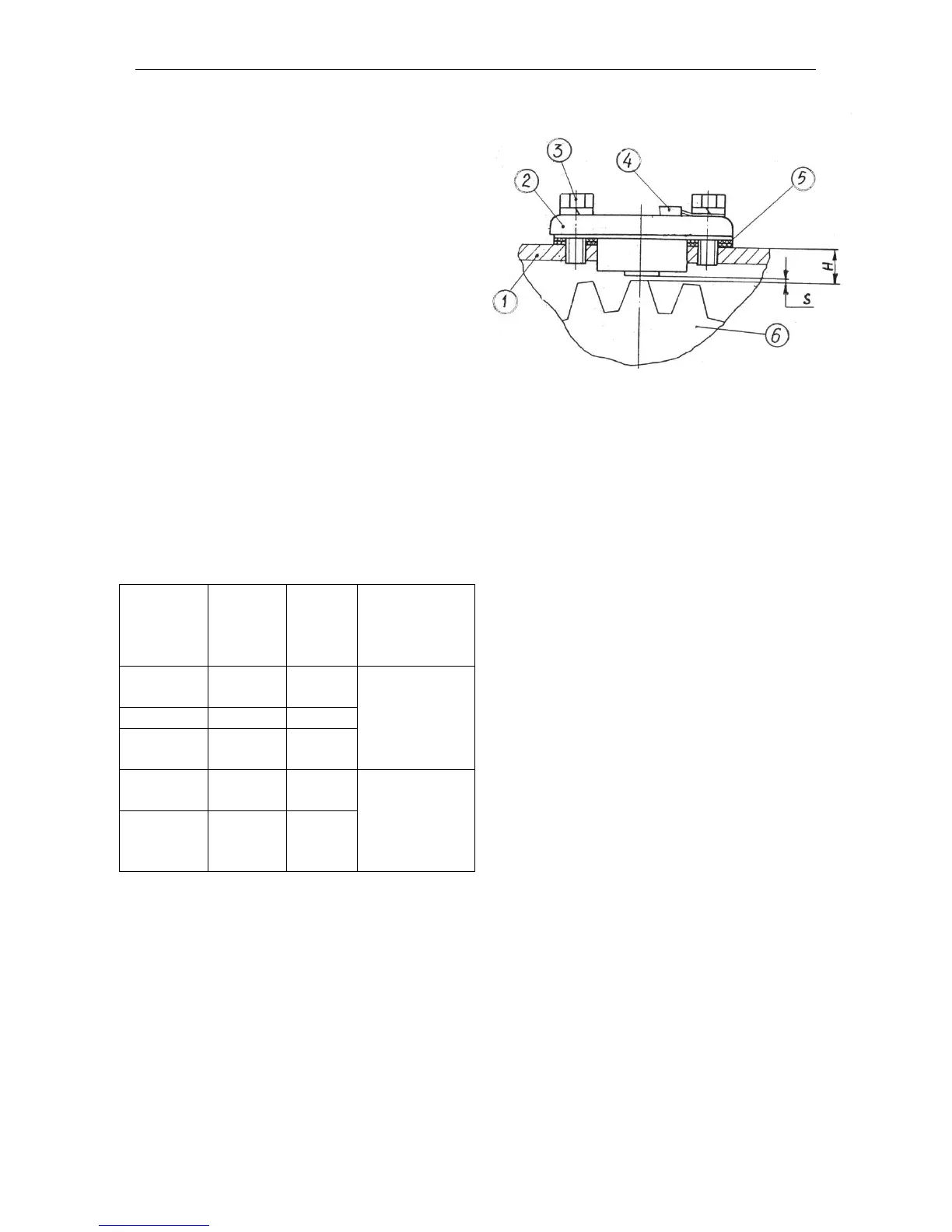
Fig. 6. Setting the speed sensors:
1 – cover of the rear axle cover;
2 – speed sensor (BV1, BV2);
3 – bolt;
4 – ground wire;
5 – adjusting spacers;
6 – final pinion.