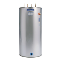
Section 1.0 – Introduction
1.1 Description of the System ...................................................................................................1
1.2 Technical Support ...........................................................................................................1
1.3 Capacity ......................................................................................................................1
Table 1: Model “D” Fre-Heater Technical Specifications .................................................................. 2
Section 2.0 – Installation
2.1 Inspection ................................................................................................................... 3
2.2 Fre-Heater Location ........................................................................................................ 3
2.3 Leveling ..................................................................................................................... 3
Figure 1: 50-Gallon Model “D” Fre-Heater
3
⁄4" Water Connection Tank .................................................. 4
Figure 2: 80-Gallon Model “D” Fre-Heater
3
⁄4" Water Connection Tank .................................................. 4
Figure 3: 119-Gallon Model “D” Fre-Heater 1
1
⁄2" Water Connection Tank ................................................ 4
Figure 4: Fre-Heater Top Head Layout: Water Connections, Anode Locations, and Refrigerant Piping .................5
2.4 Installing Water Piping ..................................................................................................... 6
Figure 5: Typical Hot Water Dump Valve Piping ........................................................................... 6
Figure 6: Typical Plumbing for Fre-Heater Water Connection ........................................................... 6
Figure 7: Typical Multiple-Unit Series Plumbing for Fre-Heaters (Commercial Applications) ......................... 8
Figure 8: Typical Multiple-Unit Parallel Plumbing for Fre-Heaters ...................................................... 9
Figure 9: Fre-Heater Piping Scheme ....................................................................................... 9
2.5 Refrigeration Connections ................................................................................................10
2.6 Heat Pumps ................................................................................................................12
2.7 Ice Machines ...............................................................................................................12
2.8 Refrigerant Charge .........................................................................................................12
2.9 Test Run .................................................................................................................... 12
Figure 10: Typical Refrigeration Connections for a Single Condensing Unit and Single-Circuit Piping ............... 13
Figure 11: Typical Single Condensing Unit with Multiple-Circuit Piping ............................................... 13
Figure 12: Typical Dual Condensing Unit Piping ......................................................................... 14
Figure 13: Fre-Heater Location with Hot Gas Defrost Valve, Oil Separator, and/or Discharge Muffler in System .....14
Figure 14: Typical Heat Pump Refrigerant Piping Diagram .............................................................. 15
2.10 Electrical Connections for Model “DE” Fre-Heater ...................................................................... 15
2.11 Special Model “DE” Fre-Heater Operating Instructions .................................................................16
2.12 Maintenance ............................................................................................................... 16
Figure 15: Model “DE” Fre-Heater Wiring Schematic .................................................................... 17
Table of Contents
Model “D” Fre-Heater
INSTALLATION AND OPERATION MANUAL
Mueller Model D Fre-Heater Installation and Operation Manual Eective March 1, 1993
Part No. 8800430 Revised November 6, 2019

 Loading...