EasyManua.ls Logo

Muir VRC4500 - User Manual

Default Icon
9 pages
Print Icon
To Next Page IconTo Next Page
Loading...
1
VRC4500 - VERTICAL WINDLASS
INSTALLATION AND INSTRUCTION MANUAL
(MUST BE READ PRIOR TO INSTALLATION AND OPERATION)
DESIGNED, MANUFACTURED AND SUPPLIED BY:
Muir Engineering Group Pty Ltd (HEAD OFFICE)
100 Browns Road, Kingston 7050 Tasmania Australia Tel:
ITN’L (61-3), AU (03) 6229 0600
Fax: ITN’L (61-3), AU (03) 6229 7030
Email: info@muir.com.au Web: www.muir.com.au
T h e w o r l d p o w e r i n w i n d l a s s e s & a n c h o r i n g s y s t e m s
Question and Answer IconNeed help?

Do you have a question about the Muir VRC4500 and is the answer not in the manual?

Summary

SCOPE OF SUPPLY

GENERAL DESCRIPTION

INSTALLATION

LOCATING THE WINDLASS

Proper positioning and chain path for efficient windlass operation.

ELECTRICAL INSTALLATION

Guidelines for wiring and circuit protection for electrical systems.

HYDRAULIC INSTALLATION

Recommendations for hydraulic piping size and pressure relief valves.

OPERATION

DISMANTLING THE TOP ASSEMBLY

Step-by-step guide to disassemble the windlass top assembly.

COMMISSIONING PROCEDURE

Steps for initial setup, testing, and running-in the windlass.

BOLT TORQUES

Specifies tightening torque and pre-load values for ensuring structural integrity.

LOWERING THE ANCHOR

Procedure for safely lowering the anchor using brake and clutch mechanisms.

RETRIEVAL

Steps for engaging the clutch and raising the anchor.

Clutch Operation

Detailed steps for correctly engaging the windlass clutch mechanism.

RAISING THE ANCHOR

Pre-operation checks and process for lifting the anchor.

IMPORTANT NOTES ON SAFE OPERATION

Critical safety warnings and guidelines for windlass use.

MAINTENANCE

ELECTRIC OR HYDRAULIC MOTORS

Maintenance recommendations for windlass motors.

GEARBOX

Instructions for gearbox lubrication and maintenance.

CORROSION PREVENTION

Methods for protecting the windlass from corrosive environments.

LUBRICATION

Guidance on greasing points and lubrication intervals.

GENERAL MAINTENANCE

Routine cleaning and maintenance practices for the windlass.

RECOMMENDED LUBRICANTS

List of recommended oils and greases for windlass maintenance.

BRAKE HANDLE INSTALLATION

Installation Procedure

Step-by-step instructions for correctly installing the brake handle assembly.

Overview

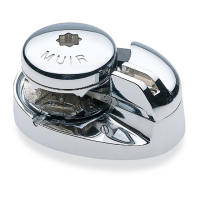
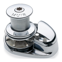
The VRC4500 Model Vertical Windlass is an anchoring system designed for marine applications, powered by an electric motor through a single-stage worm drive reduction. It consists of a gypsy and capstan mounted on a stainless steel drive shaft, supported by low-friction bearings, and mounted on a stainless steel base plate. The capstan is keyed directly to the drive shaft, and the gypsy is driven by engaging a clutch. All components are constructed from bronze or stainless steel for durability in corrosive marine environments.

Function Description:

The primary function of the VRC4500 windlass is to facilitate the deployment and retrieval of an anchor and its chain. It offers two main methods for lowering the anchor: powered deployment using the electric motor, or free-wheel deployment controlled by a brake band after disengaging the clutch. For retrieval, the anchor is raised by operating the electric motor, with the clutch fully engaged and locked. A clutch handle, fitted into the clutch nut, is used to de-clutch the drive, allowing the chain gypsy to free-wheel. The brake band controls the run of the anchor and chain during deployment.

Important Technical Specifications:

  • Model: VRC4500 Vertical Windlass
  • Gypsy: Designed to suit 12.5mm U2 STUD LINK chain.
  • Finish: Fluted Capstan Finish, Polished 316 Stainless Steel Finish.
  • Clutch Handle: Stainless Steel.
  • Brake: 35-degree brake.
  • Line Type: 12.5mm U2 (Kenters).
  • Gearbox Manufacturer: STM
  • Gearbox Description: Single Stage 90 Degree Worm Wheel Gearbox.
  • Gearbox Model: RMI 110 F2.
  • Gearbox Ratio: 70:1.
  • Motor Manufacturer: WEG.
  • Motor Model: 440V / 4kW / 3Ph / 50Hz.
  • Bolt Tightening Torque (Stainless Steel Class 70):
    • M8: 16.6 Nm
    • M10: 35 Nm
    • M12: 61.2 Nm
    • M16: 152 Nm
    • M20: 296.4 Nm
    • M24: 512.8 Nm
  • Pre Load (Nm):
    • M8: 10.8 Nm
    • M10: 17.2 Nm
    • M12: 25 Nm
    • M16: 46.6 Nm
    • M20: 72.7 Nm
    • M24: 104.8 Nm
  • Minimum Fall Depth To Top Of Heaped Chain:
    • Up to 1/2" (13mm): 36" (914mm)
    • 5/8" to 7/8" (16 to 22mm): 48" (1220mm)
    • 1" (25mm) and Above: 48" (1220mm) or Greater
  • Recommended Hydraulic Piping (Outside Diameter):
    • Up to 30' (9.1m) Length of Line: 5/8" (16mm)
    • Over 30' (9.1m) Length of Line: 3/4" (19mm)

Usage Features:

  • Installation: Requires careful consideration of chain path, locker depth, wrap around the gypsy (minimum 140 degrees, ideally 180 degrees), and motor/gearbox positioning. Insulation of dissimilar metals (e.g., steel/alloy deck) with rigid plastic is recommended. All mating surfaces should be coated with sealant.
  • Operation (Lowering Anchor): Can be powered down or free-wheeled. For free-wheeling, apply the brake, disengage the clutch by rotating the clutch nut anti-clockwise, then slowly release the brake to control descent. A chain stopping device should be engaged once the anchor is set to take the load off the windlass.
  • Operation (Retrieving Anchor): Ensure clutch and brake are fully engaged and locked before releasing the chain securing device. Engage the clutch by tightening the clutch top (clockwise). The anchor can then be raised by operating the control.
  • Clutch Operation: To engage the dog clutch, ensure the four drives are aligned (by inching the windlass or using the brake), then turn the clutch nut clockwise until fully engaged. Slowly slacken the brake to allow the gypsy to rotate and fully engage the drive faces.
  • Safety:
    • Not to be used for lifting people aloft.
    • Ensure no one is swimming nearby during anchor operations.
    • Keep hands, feet, hair, and clothing clear of the windlass and chain.
    • DOG CLUTCHES DO NOT SLIP; mark the chain at 5-meter intervals to prevent bringing the anchor up hard against the vessel.
    • Do not operate if stalled or overloaded.
    • Never engage the clutch while the anchor is free falling; use the brake band to control speed.
    • Engage the chain stopper and devil's claw when traveling to secure the anchor.
    • If anchor retrieval is impaired by high winds or heavy seas, ease the load by motoring slowly into the wind; the winch is not designed to propel the vessel.
    • A chain stopping device must be fitted forward of the windlass to take the mooring load off the windlass, preventing damage to the winch. If not possible, use a snubber line. Ensure the brake is fully engaged while at anchor.

Maintenance Features:

  • Electrical/Hydraulic Motors: Motors are water-resistant but require protection from sea air (e.g., water repellent spray every 6-8 weeks or protective coating). Any external paint damage should be repaired immediately.
  • Gearbox: Fill with lubricant to the level mark on the sight glass before operation. Check oil level every 6-8 weeks. Protect from moisture similar to the motor.
  • Corrosion Prevention: Denso Tape (grease tape) is highly recommended for external surfaces of hydraulic motor, hose ends, gearbox, and adaptor. Corrosion protection should be used in areas where water may lie (e.g., top of gearbox output shaft). Products like TECHTYL anti-corrosion film are suitable.
  • Lubrication:
    • Perform lubrication regularly, at least 4-6 times a year, more frequently with higher usage.
    • Check and lubricate all grease nipples before use.
    • Brake band Grease nipples: Located on each brake band lug. Apply 1-2 pumps to each. (Alternate designs without nipples require shaft disassembly, greasing, and reassembly).
    • Base Grease nipple: Located in the top flange of the base plate. Apply 3-4 pumps to lubricate the shaft rotation in the base plate bearing.
    • Grease: An extreme lithium-based grease with anti-corrosion properties suitable for marine use (e.g., BP Energrease MM-EP2) is recommended.
    • Worm Wheel Gearbox Oils (Recommended): SHELL Tivela S 320, AGIP Blasia S 320, KLUBER Klübersynth GH 6 320, MOBIL Glygoyle 320, CASTROL Alphasyn PG 320, TOTAL Carter SY 320.
    • Hydraulic Fluid (Recommended): CASTROL AWS32 or equivalent.
  • General Maintenance:
    • Twice yearly, disassemble the above-deck running gear, remove salt crust, clean, grease, and reassemble.
    • Wash salt water off all running parts with fresh water after every use to prevent corrosion.
    • Use a close-fitting cover when the winch is not in use.
    • Ensure the main drive shaft remains greased at all times.
    • Store the unit vertically or in a similar position to its installed orientation before installation.

Commissioning Procedure:

  1. Ensure all electrical wiring is completed as per the supplied diagram.
  2. Grease all nipples as shown in the diagram and described in the lubrication section.
  3. Check that the gear drive is filled with the correct quantity and type of oil.
  4. Disengage the clutch by turning the clutch nut anti-clockwise.
  5. Disengage the brake using the hand wheel.
  6. Rotate the motor by power or by the motor shaft to ensure the windlass is free to rotate.
  7. Start the windlass with no load, ensuring correct rotation direction and absence of undue noise or vibration.
  8. Continue running-in the motor and gear drive for 30 minutes. Recheck gear drive oil level and grease points.
  9. If a torque limiter is present, refer to gearbox information for adjustment details.

Muir VRC4500 Specifications

General IconGeneral
BrandMuir
ModelVRC4500
CategoryMarine Equipment
LanguageEnglish

Related product manuals