① Set the POWER switch to "ON". The function is automatically set to DC
200mA range.
② Set the ACA/DCA selector switch to ACA or DCA depending upon the signal to
be measured.
③ Set the range to the appropriate range using RANGE UP or RANGE DOWN
switch.
④ Press ZERO ADJ switch to read zero for the DC current measurement. When
pressed, “ZERO ADJ” mark is displayed. In DCA measurement, always carry
out the zero adjustment before measurements. To repeat the zero adjustment,
press to release RANGE UP or RANGE DOWN switch.
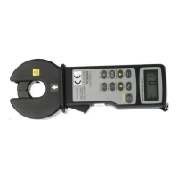
⑤ Clamp slowly and firmly around the conductor of the circuit under test with
the current transducer.
⑥ Taking measurements in a dark place or in a place where it is difficult to see
readings, use the data hold switch.
⑦ Read the displayed value.
⑧ After measurement, set the POWER switch to “OFF”.
CAUTION
The various numerals are indicated in the display in DC current measurement, even
when the clamp transducer (Jaw) is opened or closed without any input. However, this
is not abnormal. Always carry out the zero adjustment before measurements.
Note : Clamp around only one conductor in the circuit to be measured for the line
current or earth line measurement.
To measure a leakage current in a single-phase electric circuit, clamp the
two conductors together. Or clamp the three conductors together in the case
of the three-phase electric circuit.
CAUTION
Nev
er fail to keep the maximum tolerable input.
To avoid electrical shock or damage, the measurement is limited to the circuit 20A DC
or AC rms.
‐6‐