Do you have a question about the Multiaqua MHWX-09-C-1 and is the answer not in the manual?
Defines BTUH values for model sizing.
Specifies voltage and operational modes (Cooling/Heat Pump).
Lists all available model configurations.
Details system features, certifications, and testing.
Outlines procedures for shipping, storage, and handling.
Covers unit cabinet, fan motors, coils, and drain pans.
Specifies control system components and safety features.
Details electrical requirements and ambient temperature limits.
Provides dimensions, weight, and coil specifications.
Lists motor HP, ampacity, and circuit breaker requirements.
Shows CFM and nominal cooling capacities per model.
Warns about sharp edges on sheet metal parts.
Emphasizes reading the manual, checking for damage, and code compliance.
Illustrates approximate weights for different fan coil models.
Details dimensions for mounting plate components (A-L).
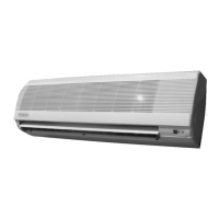
Visual representation of unit and mounting plate dimensions.
Repeats warning about sharp edges on sheet metal.
Guides on positioning, marking, drilling, and piping holes.
Provides diagrams for plate mounting and piping access.
Details routing pipes, wires, and mounting the unit.
Shows unit mounting process and wiring connections.
Covers drain slope, securing fan coil to plate, and locking clips.
Instructions for connecting refrigerant lines and condensate drain.
Illustrates drain tubing, securing, and locking clips.
Shows components of the standard wireless remote control.
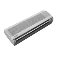
Displays the optional wired control unit.
Provides important notes for using the wireless remote controller.
Explains the meaning of LED lights on the remote controller.
Describes infrared transmission and basic power control.
Details available operation modes (COOL, DRY, HEAT, AUTO).
Explains how to select and control fan speed settings.
How to adjust and display temperature in C or F.
How to set delayed start or stop times for the unit.
Explains how to cancel timer settings and control louvers.
Describes the sleep mode for gradual temperature adjustment.
Details the humidity control (dry) mode operation.
Explains automatic heating/cooling switching logic.
How to interpret transmission signals and change batteries.
Describes LED lights and power control for wired remote.
How to select modes and fan speeds via wired control.
How to set temperature and cancel timer settings.
Details louver adjustments and auto mode logic.
Explains wiring symbols and important installation notes.
Explains wiring symbols and important installation notes.
Explains wiring symbols and important installation notes.
Explains wiring symbols and important installation notes.
Explains wiring symbols and important installation notes.
Explains wiring symbols and important installation notes.
Explains wiring symbols and important installation notes.
Explains wiring symbols and important installation notes.
Shows unit outline and overall dimensions.
Details dimensions for various mounting plate configurations.
| Type | Ductless Mini-Split |
|---|---|
| Power Supply | 1 Phase, 60 Hz |
| Refrigerant | R-410A |
| Cooling Capacity | 9, 000 BTU |
| Voltage | 208/230V |
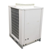
| Outdoor Unit Weight | 66 lbs |