English
10 Earth resistance tester
Functional description (cont’d)
2 spike-measuring
method
•
This method is recommended :
- where an earth resistance is higher than 10
Ω
- when it is not possible to drive auxiliary earth spikes.
•
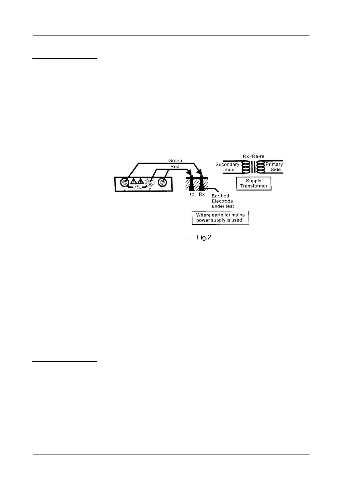
An approximate value of earth resistance can be obtained by the two
wire system as shown on Fig. 2.
•
Connect the green test cable to the terminal E, the yellow cable to the
terminal P and the red cable to the terminal C.
•
Stuck the auxiliary spike where it is possible.
•
Connect the green cable to the earth, the yellow and red cables to the
auxiliary spike as shown on following figure :
•
Then, perform a voltage measurement (position EARTH VOLTAGE +
TEST ON/OFF) to make sure that earth voltage on terminals is
< 10 V.
•
Rotate the function switch to « 200
Ω
» range position.
•
Press "TEST ON/OFF" to test. The measured value is displayed on
the screen.
•
If the display shows « 1 », rotate the switch to « 2000
Ω
» position
and test again.
The reading obtained is an approximate earth resistance value :
Rx = Re – re
Rx = true earth resistance
Re = indicated value
re = auxiliary spike resistance
Note
•
The measurement current is less than 2mA. There is no risk of
tripping mains RCD devices especially when the earth electrode
is disconnected before starting the test, as recommended.
•
The LED in front face will lit in red, when the measuring
configuration is as shown in figure 1.