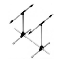
Centre of Gravity Gauge # 69 3054
First flight nerves? Actually, test-flying a model aircraft should never
present any real problems provided that two essential factors are
correct: the longitudinal dihedral (wing / tail incidence) and the
Centre of Gravity (CG).
Both these values can be calculated, or you can ask the manufacturer
or just read the building instructions supplied with your MULTIPLEX
kit. But - what is the best method of transferring those values to the
model?
The MULTIPLEX CG gauge # 69 3054 and incidence gauge # 69 3053
solve the problem completely. The CG gauge is designed to cope
with models weighing up to 10 kg all-up, and the measurement
range is 30 and 150 mm from the leading edge, i.e. it can cope with
a parallel-chord wing with a chord of up to about 450 mm.
Assembling the CG gauge
Join the two pairs of base plates 10 using four screws 30 each, and
insert the base rails 20 and uprights 22 before you tighten the screws.
Glue together the bearing brackets 11 in pairs using cyano, then fit
them on the uprights 22. Assemble the two-part supports 12 and
check that the scale rails 23 fit through them. Attach the supports
12 to the bearing brackets by inserting the bearing pins 31. Slide
the scale rails 23 through the supports 12. Fit the stop-pieces 13 and
trim weights 14 and slide them along until they butt up against the
supports. Now set the scale rails 23 exactly horizontal. With a sharp
pencil mark a point immediately adjacent to the stop-pieces. Remove
the scale rails and glue the graduated rule 24 exactly over the pencil
mark, noting the 45 mm position. Position the scale rails with the
printed value in line with the marked distance from the pivot point.
Fix the scale rails to the supports with a drop of cyano. Apply the
strips of foam tape 32 to the underside of the base rails, and stick
two pieces of foam rubber sheet 33 to each of the supports. Apply
the MULTIPLEX placard 34 to the centre of the transverse joiner 21.
Fit the transverse joiner in the base plates 10 to complete the
assembly procedure.
Using the CG gauge
Balancing a model at the prescribed Centre of Gravity
Set the correct CG position on one stop piece 13 (using the scale),
i.e. set the calculated CG position or the position stated by the model
manufacturer, then adjust the trim weight 14 to set the scale rail
level. Repeat the procedure on the other side. If necessary, adjust
the position of the transverse joiner to suit the width of the model’s
fuselage. Assemble the model completely, not forgetting the tail
panels and the flight battery (if used) and place it on the gauge with
the wing leading edge resting against the stop pieces. Add lead
ballast or re-position the internal fittings (receiver battery, flight pack
etc.) until the model balances level (don’t forget to replace the
canopy each time).
Tip: if you find that you have to add lead to correct the CG you can
work out the approximate weight required using an electronic letter
scale or spring balance. Set the required value on the stop pieces
and place the model on the CG gauge with the leading edge against
the stop pieces. We will assume that the model is tail-heavy: invert
the letter scale or balance and zero the pointer or indicator. Now
press the unit down against the top of the fuselage nose until the
model is horizontal, then read off the value on the scales. Weigh
out the ballast, check the CG again with the lead installed, and then
fix the ballast inside the fuselage
very securely.
Measuring the CG position after flight testing
Assemble the model completely, place it on the CG gauge and adjust
its position until the model balances level. Now slide the stop-pieces
up against the leading edge and read off the value on the scale.
Remove the model from the gauge and set the scale rails horizontal
by adjusting the trim weight 14. As a final check replace the model
on the gauge and check that it remains horizontal. You can now
read off the measured CG position accurately and write it down.
This “fine-tuning” is only really effective with lightweight models.
Lead ballast for balancing - the MULTIPLEX accessory range
Copper-plated lead shot 4.5 mm Ø 100 g # 71 2765
Copper-plated lead shot 4.5 mm Ø 500 g # 71 2766
Lead blocks L x W x H 50 x 30 x 10 mm 2 x 160 mm 320 g # 71 2763
Lead strip (rolled sheet) 200 x 50 x 2 mm 2 x 115 g 230 g # 71 2761
Lead rod 12 Ø x 220 mm 4 x 230 g 920 g # 71 2760
* Lead is poisonous - don’t touch the bare metal!
Tip: To balance a model start by pouring lead shot into a small plastic bag and tape it to the outside of the fuselage nose.
Seal the plastic
bag,
secure the the bag of lead in the fuselage and test-fly the model. When you are satisfied that the quantity is correct, the lead shot can
be glued permanently in the fuselage nose (after removing a little lead to allow for the weight of the epoxy). Please note the following: use
as little epoxy as possible, and mix the lead shot very thoroughly into the previously mixed resin. Pour the epoxy/lead mixture into the
fuselage and leave it propped up in an attitude where it won’t shift.
Caution: mixing up a large quantity of resin (about 100 g lead / resin mixture or more) results in an exothermic reaction which produces a
dangerous amount of heat. If possible place the nose of the (GRP) fuselage in a bowl of cold water to cool it, otherwise mix several smaller
doses of resin.
Parts list - CG gauge
Part No. Description Material Dimensions
No off
1 1 Assembly instructions
Plastic parts
10 4 Base plate Inj. moulded plastic Ready made
11 4 Bearing bracket Inj. moulded plastic Ready made
12 4 Support Inj. moulded plastic Ready made
13 2 Stop-piece Inj. moulded plastic Ready made
14 2 Trim weight Inj. moulded plastic Ready made
Aluminium parts
20 2 Base rail Aluminium section 8 x 8 x 245 mm
21 1 Transverse joiner Aluminium section 8 x 8 x 345 mm
22 2 Vertical post Aluminium section 8 x 8 x 245 mm
23 2 Scale rail Aluminium section 8 x 8 x 345 mm
24 2 Graduated ruler Printed film 8 x 170 mm
Accessories
30 8 Screw Metal 2.9 Ø x 9.5 mm
31 2 Pivot pin Metal 2 Ø x 16 mm
32 4 Foam rubber strip for base Plastic 4 x 9 x 20 mm
33 4 Foam rubber support Plastic 2 x 16 x 16 mm
34 1 MULTIPLEX sticker Printed film 9 x 40 mm
Anleitung Schwerpunktwaage Nr.:82 5935 - Seite 2 von 6
 Loading...