Do you have a question about the Multitech MultiConnect Conduit MTCAP and is the answer not in the manual?
Lists the items included in the device package, including the Access Point, Ethernet cable, power supply, and quick start guide.
Details the physical connectors and status indicator LEDs on the MTCAP device, explaining their function.
Provides instructions and visual guidance for inserting a micro SIM card into the MTCAP device's SIM slot.
Guides users on how to connect the MTCAP device using Ethernet and power cables for initial setup.
Explains how to access the Access Point's web management interface by logging into the AEP using default credentials.
Instructs users on changing the default password for enhanced security after initial login.
Details the process of configuring the device's time zone, date, and current time for accurate operation and logging.
Provides steps to configure Point-to-Point Protocol (PPP) settings for cellular connectivity, including dial-on-demand.
Explains how to set up authentication protocols, username, and password for cellular PPP connections.
Guides users through setting static IP addresses, network masks, and DNS server information for the Ethernet port.
Details how to configure HTTP/HTTPS redirection and access methods (LAN/WAN) for managing the device.
Instructs users to save and restart the device after completing initial configuration settings.
Provides initial steps and configuration parameters for setting up LoRa network connectivity and parameters.
Details the necessary tools and steps for physically mounting the MTCAP device using its bracket.
Offers guidance on selecting an optimal placement for the MTCAP to ensure strong LoRa signal reception and transmission.
Directs users to developer guides for safety information and states compliance with relevant EU directives.
Contains copyright notices, trademark information, and disclaimers regarding the publication and the product.
The MultiConnect® Conduit™ Access Point (MTCAP) is a robust device designed to facilitate the connection of thousands of IoT assets to the cloud, leveraging the LoRaWAN® protocol. It serves as a crucial component for expanding LoRa network coverage, particularly in areas that are typically difficult to reach. The MTCAP is capable of forwarding user data packets between LoRa endpoints and a centrally located network server, which can reside in the cloud, a data center, or a public network. This functionality makes it an ideal solution for various IoT deployments requiring extensive and reliable connectivity.
The MTCAP device ships with essential components to ensure a quick and straightforward setup. The package includes the MultiConnect Conduit Access Point unit itself, a 5 Volt power supply, an RJ45 Ethernet cable, and a Quick Start guide. It is important to note that using a different power supply than the one provided may damage the device and void the warranty. In case a replacement 5 V power supply is needed, users are advised to contact MultiTech Systems directly.
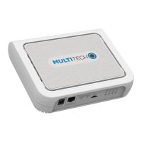
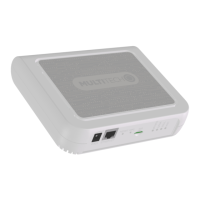
The device features several connectors and LEDs that provide visual feedback on its operational status and facilitate various functionalities. The connectors include a 5 Volt power jack for connecting the power supply, an RJ45 Ethernet jack for network connectivity, and a SIM slot available on specific models (-LEU1 and -LNA3) for cellular connectivity. There is also a Reset button, which can be used to reboot the device or restore it to factory defaults. For -002L models, a WPS switch is included for Wi-Fi pairing.
The LEDs on the MTCAP offer clear indications of the device's status. The STATUS LED blinks when the operating system is fully loaded, signaling that the device is ready for operation. The LORA LED illuminates when the LoRa software is active, indicating that the LoRa functionality is operational. For models with cellular capabilities (-LEU1 and -LNA3), the CELL LED lights up when there is power to the cellular radio and blinks when the SIM card is successfully registered with the carrier. The WIFI LED, present on -002 models, lights up when a Wi-Fi connection is established. Additionally, the Ethernet connector has two LEDs: the left LED (Ethernet Link) blinks to indicate transmit and receive activity on the Ethernet link and shows a steady light when a valid Ethernet connection is established. The right LED (Ethernet Speed) lights up when the Ethernet is linked at 100 Mbps; if it is not lit, the Ethernet is linked at 10 Mbps.
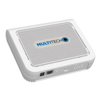
Installing a SIM card is a straightforward process for cellular-enabled devices. Users will need a micro SIM card from their network provider. The installation involves aligning the notched edge of the SIM card with the contact side facing down, as shown in the provided image, and sliding it completely into the SIM holder.
Cabling the MTCAP involves connecting the Ethernet cable to the Ethernet port on the device and to a PC, then connecting the power supply to the power jack. After connecting the power supply, users should wait approximately 30 seconds for the device to power up.
Once the device is powered up and connected, users can log in to the AEP (Application Enablement Platform) for configuration. This is done by opening an Internet browser and entering the device's default IP address (192.168.2.1) in the address field. The login page will appear, prompting for a username and password. The default username is "admin" and the default password is "admin." After entering these credentials and clicking "Login," the First Time Setup Wizard will launch.
For security reasons, it is strongly recommended to change the default password. This can be done within the setup wizard by clicking "Next" on the Welcome panel, entering "admin" in the Current Password field, and then entering and confirming a new password in the respective fields before clicking "Next."
The setup wizard also guides users through setting the time zone, time, and date. Users can type today's date in the specified format or use the calendar (data picker), enter the current time in 24-hour format, and select the appropriate time zone before proceeding.
For models equipped with cellular radios, configuring PPP (Point-to-Point Protocol) is a key step. To enable PPP, users should check the "Enable" option, which allows the device to function as a cellular device. The "Dial-on-Demand" option can be checked to configure the device to establish a PPP connection only when there is outgoing IP traffic, bringing the connection down after a specified idle timeout. The default idle timeout is 180 seconds, but this can be adjusted. Users also need to type the APN (Access Point Name) provided by their wireless service provider. After configuring these settings, clicking "Next" will save them.
Setting up PPP authentication is another important step for cellular connectivity. Users can select an authentication protocol type (pap, chap, or pap-chap), with "None" as the default. Optionally, a username and password for the remote peer can be entered for authentication, with both fields limited to 60 characters. Clicking "Next" will exit the wizard after these settings are applied.
Configuring the IP address and network information for the Ethernet port is crucial for network integration. It is advised to leave the interface static unless a DHCP server is used on the network. If DHCP client is selected, users need to know the address assigned to the Conduit. The configuration involves typing the device's IP Address, entering the network Mask, and optionally entering the Gateway address, Primary DNS server address, and Secondary DNS server address (these optional fields are not displayed when Cellular is enabled). After entering the necessary information, clicking "Next" will save the settings.
For access configuration, when Cellular is disabled, the default settings enable HTTPRedirect to HTTPS via LAN. Users should be aware that enabling HTTPS via WAN can increase security risks by allowing web users to access the WAN interface. To configure this, users can check or uncheck "Enabled" under HTTPRedirect to HTTPS, enter a port or use the default value, and select either "Via LAN" or "Via WAN." Under HTTPS, a port can be entered or the default value used. Finally, clicking "Finish" completes the access configuration.
After completing the basic configuration, users need to save and apply the settings by clicking "Save and Restart" near the top of the left sidebar. The device will restart, and upon logging back into the AEP interface, the Dashboard under Cellular should display "Link is Up" for PPP state, though a short wait may be required.
To get started with LoRa, users should log into the web management interface if not already logged in. LoRa Network Server Configuration can be accessed by navigating to "Setup > LoRa Network Server" on the left sidebar. Here, various settings can be modified as needed. For advanced settings, detailed field descriptions, and information on configuring endpoints, users can refer to the MultiTech developer website. Key fields include "Enabled" (checked for both NA and EU models), "Frequency Band" (915 for NA, 868 for EU), "Frequency Sub Band" (1 to 8 for NA, NA for EU), "Additional Channels" (NA for NA, 863.5-867.5 MHz and 869.1-869.5 MHz for EU), "Name" (LoRa network name, case sensitive), and "Passphrase" (LoRa network security passphrase, case sensitive).
For additional information on configuring LoRa devices to communicate with the MTCAP, users can visit the MultiTech website. Specific help for LoRa and AEP can be found at dedicated developer links provided in the manual.
Mounting the MTCAP is facilitated by a mounting bracket included with the device. Users will need a screwdriver, drill, and four #6 screws with anchors (not provided). The process involves determining the desired mounting location, marking where the screws will go, drilling holes and inserting anchors, securing the mounting bracket with screws, and finally attaching the device to the bracket and rotating it to lock it into place.
Determining an optimal location for the MTCAP is crucial for performance. It is recommended to select a location central to all devices intended to connect to the MTCAP and to place the device as high as possible, such as near the top of a wall. Obstructions like thick walls, reflective surfaces, or metal should be avoided as they can weaken the signal. The LoRa antenna's location on the device should be noted, as the signal will radiate strongest from that side. The LoRa antenna is omni-directional, but for best results, the device should be mounted so the LoRa antenna is in a vertical position near the top of a wall. Conducting a site survey to test signal strength in different locations before final mounting is recommended.
For safety and regulatory content, users should refer to the MultiConnect Conduit Access Point Developer Guide, available on the MultiTech website. MultiTech declares that this device complies with the essential requirements and other relevant provisions of Directive 2014/53/EU, and the declaration of conformity can be requested from their support portal.
| Category | Wireless Access Point |
|---|---|
| Connectivity | Ethernet, Cellular, LoRa, Wi-Fi |
| Processor | ARM Cortex-A8 |
| Ethernet Ports | 1 x 10/100 BaseT Ethernet |
| LoRa Frequency | 868 MHz |
| Cellular Technology | 4G LTE |
| Wi-Fi | 802.11 b/g/n |
| Serial Ports | 1 x RS-232 |
| USB Ports | 1 x USB 2.0 |
| Model | MultiConnect Conduit MTCAP |