This document describes the Multibus door panel systems, specifically models MB-09, MB-10, MB-02, MB-04, MB-03, and MB-05, along with their wiring diagrams, programming features, and technical specifications.
Function Description
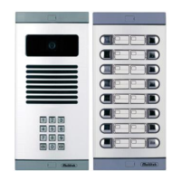
The Multibus door panel systems are designed for apartment buildings, providing a comprehensive solution for access control, communication, and security. These systems allow residents to communicate with visitors at the door, grant access, and monitor external areas using integrated cameras. The panels support multiple blocks and can be integrated with guard units for enhanced security. Key features include:
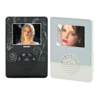
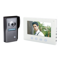
- Door Panel Communication: Enables two-way audio communication between visitors at the door panel and residents inside their apartments.
- Access Control: Allows residents to open the door remotely using a password or by pressing a button on their indoor monitor.
- Video Monitoring: Integrates with external cameras and a door panel camera to provide visual surveillance of the entrance and surrounding areas.
- Programmable Features: Offers extensive programming options for assigning door numbers, entering room names, defining door opening passwords, and configuring block numbers.
- Scalability: Supports a varying number of apartments and external cameras, making it suitable for different building sizes.
- Intercom Functionality: Facilitates communication within the building, including calls to guard units.
Important Technical Specifications
- Door Panel Models: MB-09, MB-10, MB-02, MB-04, MB-03, MB-05.
- Power Supply: Typically 12V DC for cameras and 18V DC from a PS-18E adaptor (220V AC input).
- External Camera Support: A maximum of 4 external cameras can be connected to a single door panel. The total number of external cameras connected to a building cannot exceed 5.
- Video Transmission: FS-4201SR, FS-4401S, or FS-4401R video transmissions must be used according to cable distance.
- Door Numbering: Maximum door number may be 4.
- Block Numbering: The system supports block numbers up to 30.
- Door Unlock Duration: Adjustable from 1 to 99 seconds.
- Password Length: 4-digit passwords for door opening.
- Cable Types for Wiring:
- Sound System (3 cables): KPD-V 3x0.5mm2.
- Sound System (4 cables): KPD-V 4x0.5mm2.
- Video System (No Guard/Doorkeeper, 12 Floors/80 Rooms, 4 cables): Multitek DT5 or H03VH-H 2x1mm2 (red, green), KPD-V 2x0.5mm2 (yellow, black, pink). For more floors/apartments, use H03VH-H 2x2.5mm2 cable.
- 6 Floors (Up to 40 floors) with CAT5/CAT6/DT8: Specific connection diagrams are provided.
- Multibus (up to 6 floors/40 monitors, longest cable approx. 30m): CAT5/CAT6/CAT8 or MULTITEK DT5.
- Multibus (up to 12 floors/80 monitors, longest cable approx. 50m): MULTITEK DT5 or H03VH-H 1X2X1mm2 and KPD-V 3X0.5mm2.
- Multibus (more floors): H03VH-H 1X2X2.5mm2 and KPD-V 3X0.5mm2.
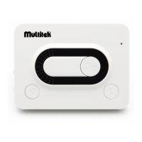
- Video Amplifiers (V-DIST 4+1): Used to amplify video signals in column-type installations. A 75 ohm resistor must be installed between the black (video) and green (GND) cables in the last circle of each column, and between the monitors 75 ohm resistances must be removed. An important 75 ohm terminating resistor must be fitted between the V-DIST-4 + 1 video amplifier and the VINPUT and GND terminals.
- MB-DIST Video Distributors: Used to connect 1 MB-DIST video distributor to each floor in horizontal installations. PS-18E adaptors are used in the MULTIBUS system (1 for up to 40 apartments, 2 for up to 100 apartments, 1 RED-18E for more than 100 apartments). A 75 ohm jumper behind all monitors connected with the video distributor must be short-circuited.
- DIP Switch Group: Used for room numbering, supporting up to 256 rooms.
Usage Features
- Calling by Name: Residents can be called by entering the ENT key, then selecting the name using up (2) and down (8) keys, and confirming with ENT.
- Programming the Panel:
- Access the program menu by pressing ENT and 99 digits.
- Navigate the menu using up (2) and down (8) keys.
- Confirm selections with ENT.
- Change Password: Enter the current program password, then a new password. Consecutive digits (e.g., 1234, 5678) are not accepted.
- Door Number Assignment (DOOR NR): Assign a door number (max 4) using up (2) and down (8) keys, then ENT.
- Entering Room Names (ENTER NAMES): Select ENTER NAME, press ENT, enter the flat number, then write the room name using the keypad letters, and press ENT.
- Clear List (CLEAR LIST): Deletes all names from the list by pressing ENT.
- Block Number Definition (BLOCK NO): Select BLOCK NO, press ENT, and enter the block number (up to 30).
- Unlock Duration (UNLOCK DURATION): Adjust the door release time (01-99 seconds) using up (2) and down (8) keys, then ENT.
- Defining a Door Opening Password:
- Call the desired flat and establish conversation.
- The resident presses F1 on their monitor.
- The person at the door panel enters "99 + XYZT" (4-digit password).
- Consecutive digits are not accepted.
- Opening the Door with Password: Enter "99 + 4-digit number password" on the door panel keypad.
- Clearing Mistakes: The CLR key can be used to clear incorrect entries.
- Monitor Interaction: The image from the door panel camera and external cameras can be viewed by repeatedly pressing the button on the monitor.
Maintenance Features
- AEEE Regulations: The device obeys the rules of AEEE regulations, indicating compliance with waste electrical and electronic equipment directives for proper disposal and recycling.
- Error Tones: The door panel provides an error tone if an invalid password is entered, prompting the user to re-enter.
- Wiring Diagrams: Detailed wiring diagrams are provided for various configurations, including security cameras, indoor units, and different cable types, facilitating installation and troubleshooting.
- Volume Adjustment: Microphone and speaker volume levels can be adjusted on the MB-09/MB-10 outdoor unit connection terminals.
- Troubleshooting: The manual provides specific notes for troubleshooting, such as ensuring 75 ohm jumpers are short-circuited for video distributors and checking cable types for different distances and floor counts.