Description
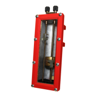
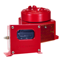
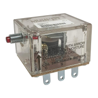
The L129 Series Lube Level Swichgage instrument is a com-
bination lube level indicating gauge with adjustable low and
high limit switches. It provides protection against low oil level or high level
caused by overfill or fuel or water seepage into the crankcase. A 6-3/4 inch
(171 mm) deep sight gauge allows you to check the condition and level of
your oil without shutting down the equipment.
Fingertip adjustable limit switch contacts are adjustable thru 4-7/8 inch (122
mm) range. When the float touches the high or low limit contact, a normal-
ly open circuit will close which can activate alarms and/or shutdown the
equipment.
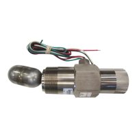
There are two models in the L129 Series: L129 and L129CK1. The L129
model is designed for grounded, low voltage electrical systems. It features a
one-wire-to-ground electrical circuit. The L129CK1 is designed for applica-
tions requiring a three-wire, above ground electrical circuit. It features
ungrounded contacts and a conduit hub for electrical wiring connection.
Specifications
Case: Die Cast Aluminum.
Lens: Tempered Glass.
Maximum Working Pressure: 10 psi (68.9 kPa) [0.69 bar].
Process Connection: 1/2 NPT.
Float Material: Brass.
Contact Rating: 2 A @ 30 VAC/DC, pilot duty.
Flow Restrictor Plug
Order Separately
Flow Restrictor Plug restricts oil flow between the
crankcase and the L129 Series. It is typically used on
some mobile applications such as marine and mobile
equipment. Part no. 15050241.
Installation Instructions for
L129 Series Level Swichgage
®
instrument
L-95006N
Revised 06-06
Section 15
00-02-0174
Please read the following information before installing. A visual inspection of this product for
damage during shipping is recommended before mounting.
GENERAL INFORMATION
BEFORE BEGINNING INSTALLATION OF THIS MURPHY PRODUCT
✔✔
Disconnect all electrical power to the machine.
✔✔
Make sure the machine cannot operate during installation.
✔✔
Follow all safety warnings of the machine manufacturer.
✔✔
Read and follow all installation instructions.
8 in.
3-3/16 in.
2-31/64 in.
1-1/2 in.
2 in.
9-55/64 in.
4-55/64 in.
2-31/64 in.
1-1/2 in.
2 in.
Dimensions
*
L129
CAUTION:
Certain danger to human and to equipment
such as applied in a mobile or marine application may occur if
some equipment is stopped without pre-warning. It is therefore,
recommended that monitored functions be limited to alarm
only or to alarm before shutdown in such applications.
Repair Kits
Specify part number.
L129
15000888 Full Repair Kit (less castings and glass assÕy) fo r date
code T2 and later.
15000480 Bezel, Glass and Gasket Set for date code W7 and later
15000485 Glass and Gasket Set for all date codes
15050241 Restrictor plug for all date codes
L129CK1
15000480 Bezel, Glass and Gasket Set for date code W7 and later
15000485 Glass and Gasket Set for all date codes
15050241 Restrictor plug for all date codes
L-95006N page 1 of 2
*Complete with EMC Council directive 89/336/EEC regarding electromagnetic compatibility.