L-95006N page 2 of 2
NOTE: Read all instructions before beginning installation.
Mounting
1.
Determine which side of the engine to mount the L129. This will normally be the
side of the engine from which it is started. Weld a slotted mounting plate to the
engine skid or attach the mounting plate to the crankcase. If a mounting plate is
not used, a support strap is recommended (see Typical Installation below).
2.
Install the shockmounts in the threaded holes provided in the mounting bosses on
the rear of the L129. NOTE: We recommend using the shockmounts provided
to minimize “contact bounce” resulting in improper operation.
3.
Attach the L129 to the mounting plate as shown below but do not tighten TOO
TIGHT since you will have to adjust the L129 later in the installation process.
Connecting Hoses and Fittings
1.
DRAIN THE CRANKCASE. If the crankcase does not have an auxiliary plug or
connection, connect the L129 to the crankcase drain plug connection. This con-
nection will n
ormally be a straight (parallel) thread which seals with a copper or
fiber washer. NOTE: If the drain plug on the crankcase is used for the connection,
we recommend installation of a tee to allow draining of the crankcase for service.
2.
Flexible hose or rigid pipe can be used to attach the L129 to the engine
crankcase. Flexible hose is to be 1/2 in. (13 mm) I.D. minimum and made of
quality material. Use of flexible hose will allow you to adjust the height of the
L129 to properly reflect the oil level in the crankcase. Also, a swivel connection
on one end of the hose will assist in properly aligning the L129.
Rigid pipe is to be 1/2 inch pipe. If the length of the pipe is relatively short, no
additional support for the L129
may be needed, although it is recommended. A
pipe union is provided in the installation kit.
Attach the hose or pipe from the L129 process connection (1/2 NPT) to the
crankcase.
3.
For vented crankcases, install the tube fitting and copper cane provided in the
installation kit into the top of the L129. Venting to atmosphere will allow the oil
level to rise in the L129 to the same level as in the crankcase, (the pressure/vacu-
um in the L129 and the crankcase must be equal). If the crankcase develops a
positive (pressure) or negative (vacuum) pressure, you MUST connect the
L129 vent back to the crankcase. If you do not do this, the L129 will indicate
high level with a pressurized crankcase and a low level with a vacuum crankcase.
In extreme cases a pressurized system will blow oil out the vent tube or in vacu-
um crankcases can suck oil out of the L129.
To vent the L129 back to the crankcase, install a 1/4 inch (6 mm) O.D.
or larg-
er tubing (copper or flexible) from the L129 vent fitting to a point in the
crankcase above the full oil level or in the fill pipe that is not
restricted by baf-
fles, filters or other obstructions. If connecting directly into the crankcase, be
sure the entry point is clear of oil splash
that can plug the tube opening.
4.
Refill the crankcase to proper oil level. With the engine running and warm, loosen
the L129 from the mounting bracket and adjust the L129 so that the oil level shows
approximately midway or above in the sight glass. Tighten shockmount nuts.
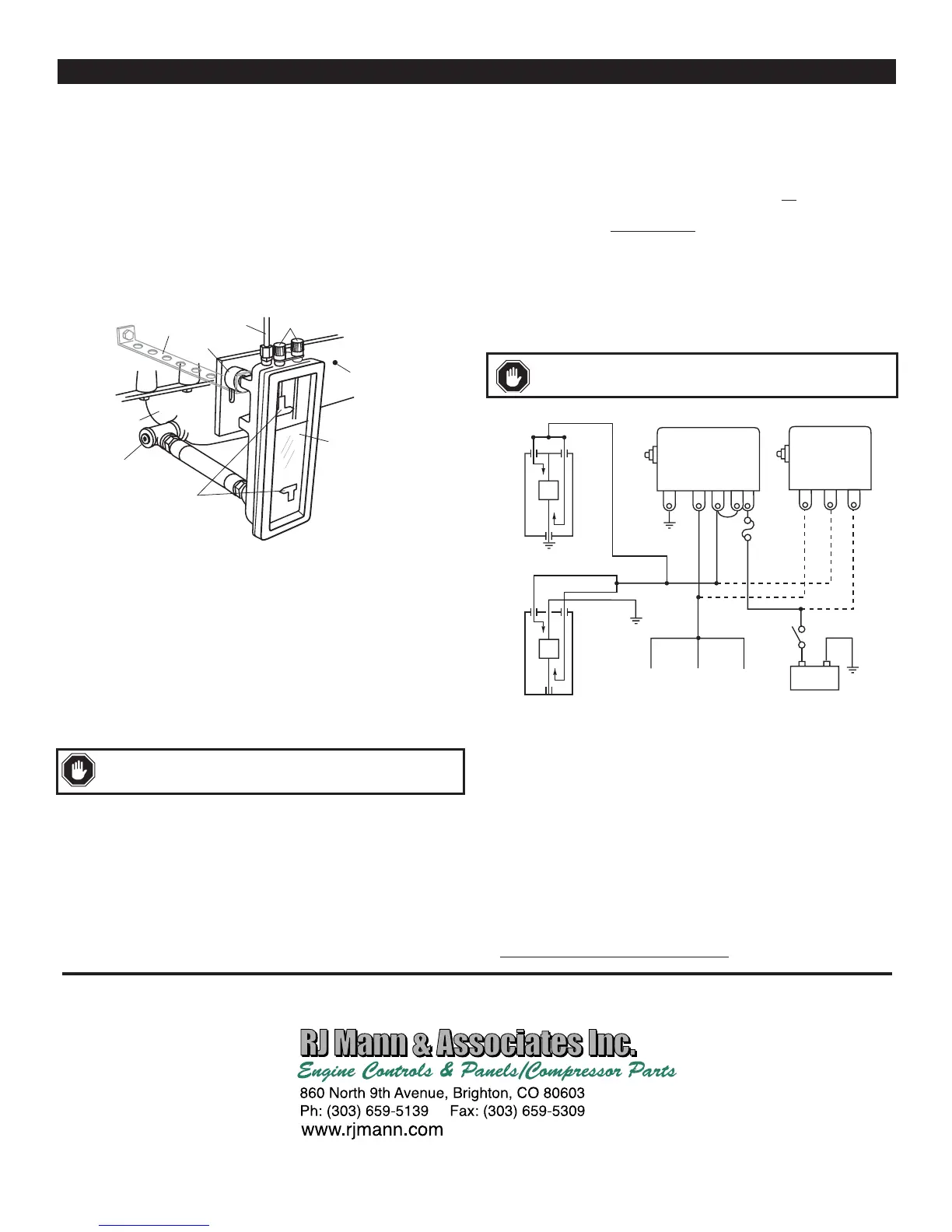
Wiring
Follow appropriate wiring for the alarm or engine shutdown system you are using.
Diagrams below are shown with the float in the “full” position.
Operation Test
The following test is to be performed after the L129 has been installed and the
crankcase has been filled to the proper oil level.
1.
With equipment running, turn the high and low adjust knobs one at a time until
they “make” contact with the float. When contact is made the alarm or shutdown
circuit should actuate.
2.
Return high and low adjustment knobs to the proper contact position before
operating equipment.
Warranty
A limited warranty on materials and workmanship is given with this FW
Murphy product. A copy of the warranty may be viewed or printed by going
to www.fwmurphy.com/support/warranty.htm
INSTALLATION and OPERATION
518PH
C S
117PH
B
G NC
SW1 SW2
B
BLACK
RED
WHITE
HI
HI LOW
LOW
COM.
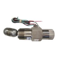
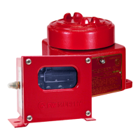
L129
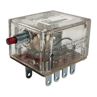
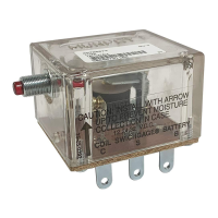
Magnetic Switches
L129CK1
_
+
Ignition
Coil
Rack Pull
Solenoid
Fuel
Valve
Battery
CAUTION:
WARNING: If both flexible hose and shockmounts are used, a
gr ound wir e must be added between the L129 and the engine.
Customer Supplied
Support Strap
Mounting
Plate
Shockmount
Vent
Contact Adjustment Knobs
High and Low
Contacts
Tee
Crankcase
Sight
Glass
Typical Installation
Contact Rating: 2 A @ 30 VAC/DC, pilot duty.
perform all wiring connections with the battery
disconnected. Observe all contact ratings and voltages.
 Loading...