EasyManua.ls Logo

Murphy VS2 User Manual

Murphy VS2
8 pages
To Next Page IconTo Next Page
Page #1 background imageLoading...
Page #1 background image
Shock/Vibration Control Switches
Installation Instructions
Models: VS2, VS2C, VS2EX, VS2EXR, VS2EXRB and VS94
GENERAL INFORMATION
Please read the following instructions before installing. A visual inspection of this product for damage during shipping is recommended before
mounting. It is your responsibility to have a qualified person install the unit, and make sure installation conforms with NEC and local codes.
Model VS2EX
LISTED
*
WARNING
BEFORE BEGINNING INSTALLATION OF THIS MURPHY PRODUCT
Disconnect all electrical power to the machine.
Make sure the machine cannot operate during installation.
Follow all safety warnings of the machine manufacturer.
Read and follow all installation instructions.
VS-7037N
Revised 04-05
Section 20
(00-02-0185)
R
VS-7037N page 1 of 8
Description
The Murphy shock and vibration switches are available in a variety of
models for applications on machinery or equipment where excessive
vibration or shock can damage the equipment or otherwise poses a
threat to safe operation. A set of contacts is held in a latched position
through a mechanical latch and magnet mechanism. As the level of
vibration or shock increases an inertia mass exerts force against the
latch arm and forces it away from the magnetic latch causing the latch
arm to operate the contacts. Sensitivity is obtained by adjusting the
amount of the air gap between the magnet and the latch arm plate.
Applications include all types of rotating or reciprocating machinery
such as cooling fans, engines, pumps, compressors, pump jacks, etc.
Models
VS2: Base mount; non hazardous locations.
VS2C: C-clamp mount; non hazardous locations.
VS2EX: Explosion-proof; Class I, Div. 1,
Groups C and D.
VS2EXR: Explosion-proof with remote reset.
VS2EXRB: Explosion-proof; Class I, Div. 1, Group B; with
remote reset.
VS94: Base mount; non hazardous locations, NEMA 4X/IP66.
Remote Reset Feature (VS2EXR,
VS2EXRB and VS94 only)
Includes built-in electric solenoid which allows reset of tripped unit from a
remote location. Standard on VS2EXR and VS2EXRB. Optional on
VS94 (options listed below).
-R15: Remote reset for 115 VAC
-R24: Remote reset for 24 VDC
Time Delay Option (VS94 only)
Overrides trip operation on start-up. For VS94 series models, the delay
time is field-adjustable from 5 seconds up to 6-1/2 minutes with a 20-
turn potentiometer (15 seconds per turn approximately). Options listed
below:
-T15: Time delay for 115 VAC
-T24: Time delay for 24 VDC
Space Heater Options (VS94 only)
This optional space heater board prevents moisture from condensing
inside the VS94 Series case. Options listed below:
-H15: Space heater for 115 VAC
-H24: Space heater for 24 VDC
Warranty
A limited warranty on materials and workmanship is given with this FW
Murphy product. A copy of the warranty may be viewed or printed by going
to www.fwmurphy.com/support/warranty.htm
Question and Answer IconNeed help?

Do you have a question about the Murphy VS2 and is the answer not in the manual?

Murphy VS2 Specifications

General IconGeneral
BrandMurphy
ModelVS2
CategorySwitch
LanguageEnglish

Summary

General Information

Safety Warning

Critical safety instructions before beginning installation of the Murphy product.

Product Description

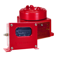
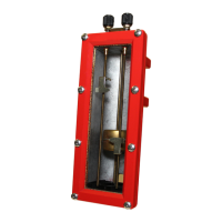
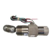
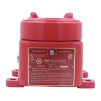
Overview of shock and vibration switches and their applications.

Available Models

Lists and briefly describes different shock and vibration switch models.

Remote Reset Feature

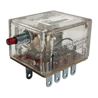
Details the optional electric solenoid for remote reset functionality.

Time Delay Option

Explains the field-adjustable time delay for VS94 models.

Space Heater Options

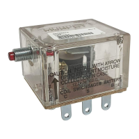
Describes the optional space heater to prevent moisture condensation.

Product Warranty

Information regarding the limited warranty for Murphy products.

Dimensions

VS2 Dimensions

Detailed physical dimensions and mounting information for the VS2 model.

VS2C Dimensions

Detailed physical dimensions and mounting information for the VS2C model.

VS2EX and VS2EXR Dimensions

Detailed physical dimensions for VS2EX and VS2EXR models.

VS2EXRB Dimensions

Detailed physical dimensions and mounting information for the VS2EXRB model.

VS94 Dimensions

Detailed physical dimensions and mounting information for the VS94 model.

Specifications

VS2 and VS2C Specifications

Technical specifications for VS2 and VS2C models, including case and contacts.

VS2EX Specifications

Technical specifications for the VS2EX model, including explosion-proof rating.

VS2EXR Specifications

Technical specifications for the VS2EXR model, including remote reset option.

VS2EXRB Specifications

Technical specifications for VS2EXRB, including Class I, Division 1, Group B rating.

VS94 Specifications

Technical specifications for VS94, including NEMA 4X, optional features.

Installation

General Installation Warning

Crucial safety instruction to disconnect power and stop the machine before installation.

C-Clamp Installation

Procedure for installing the VS2C model using the supplied C-clamp.

Mounting and Securing

Steps for firmly attaching the unit to equipment and making electrical connections.

Sensitivity Adjustment Procedure

Detailed steps to adjust the sensitivity to prevent false trips.

VS94 Time Delay Adjustment

Instructions for adjusting the time delay feature on VS94 models.

Typical Mounting Locations

Compressor Mounting Examples

Illustrations showing optimal mounting for balance-opposed and reciprocating compressors.

Pumping Unit Mounting Example

Illustration showing optimal mounting for a pumping unit.

Pump Mounting Examples

Illustrations for engine and vertical shaft pump mounting locations.

Generator Sets Mounting Example

Illustration showing optimal mounting for generator sets.

Cooling Tower Fan/Heat Exchanger Mounting

Illustration showing optimal mounting for cooling tower fans or heat exchangers.

Engine Compressor Mounting Example

Illustration showing optimal mounting for an engine compressor.

Centrifugal Compressor Mounting

Illustration showing optimal mounting for a turbine centrifugal compressor.

Internal Switches

VS2 and VS2C Switch Configuration

Diagram of SPDT switch terminals and sensitivity adjustment for VS2/VS2C.

VS2EX Switch Configuration

Diagram of SPDT switch terminals and sensitivity adjustment for VS2EX.

VS2EXR Switch Configuration

Diagram of SPDT switch, remote reset, and sensitivity adjustment for VS2EXR.

VS2EXB/VS2EXRB Switch Configuration

Diagram of switches, remote reset, and sensitivity adjustment for VS2EXB/VS2EXRB.

VS94 Switch Configuration

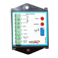
Diagram of switches, optional features, and sensitivity adjustment for VS94.

Electrical Wiring Diagrams

CD Ignition Wiring

Wiring diagrams for single or dual CD ignition systems for various models.

Electric Motor Wiring

Typical wiring diagram for connecting the switches to electric motors.

Ignition/Diesel Wiring

Wiring diagrams for distributor ignition or diesel engine systems.

Service Parts

VS2 Service Parts

List of replacement part numbers for the VS2 model.

VS2C Service Parts

List of replacement part numbers for the VS2C model.

VS2EX Service Parts

List of replacement part numbers for the VS2EX model.

VS2EXR Service Parts

List of replacement part numbers for the VS2EXR model.

VS2EXRB Service Parts

List of replacement part numbers for the VS2EXRB model.

VS94 Series Service Parts

List of replacement part numbers for the VS94 Series models.

Related product manuals