VS-7037N page 7 of 8
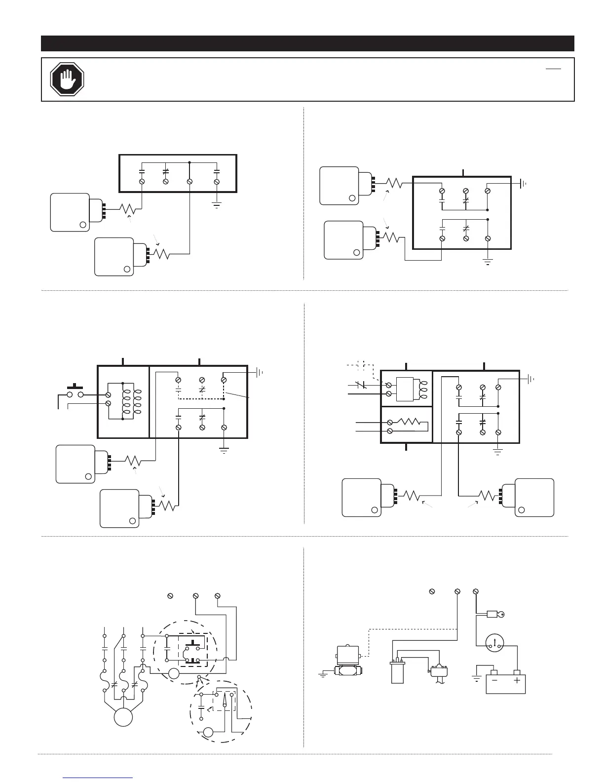
WARNING: REMOVE POWER BEFORE OPENING THE UNIT (ACCESS DOOR). STOP THE MACHINE AND DISCONNECT ALL
ELECTRICAL POWER BEFORE BEGINNING THE WIRING OPERATION. IT IS YOUR RESPONSIBILITY TO HAVE A QUALIFIED
PERSON INSTALL AND WIRE THE UNIT, AND MAKE SURE IT CONFORMS WITH NEC AND APPLICABLE CODES.
ELECTRICAL
To good
engine ground
CD Ignition
1
CD Ignition
2
Ignition Coil
Distributor
Battery
Ignition
Switch
Ammeter
Diesel Fuel
Shutoff Valve
VS2, VS2C, VS2EX, VS2EXR, VS2EXRB and VS94
Typical Wiring Diagram for Distributor Ignition or Diesel
VS2, VS2C, VS2EX, VS2EXR, VS2EXRB and VS94
Typical Wiring Diagram for Electric Motors
Maintained
Contact for
Time Delay
Momentary
Contact for
Remote
Reset only
Time
Delay
2-SPDT
Switches (DPDT)
Time Delay or
Remote Reset
(Optional)
Heater Board
(Optional)
N.C.N.O.
Contacts shown in the
RESET position
Contacts shown
in the RESET position
Contacts shown
in the RESET position
Switch Terminals
N.C.
NOTE: Terminal N.O. is
terminal NO1 on models
VS2 and VS2C.
Switch Terminals
N.C.
N.O.
(see Note)
NOTE: Terminal N.O. is
terminal NO1 on models
VS2 and VS2C.
N.O.
(see Note)
N.C.N.O.
115 VAC or 24 VDC
*
115 VAC or
24 VDC
*
*
Voltage is specified
when ordered.
L1 L2 L3
MOTOR
Push-button
Station
HC
H
A
HC
Hand Off
Automatic
Selector
VS2EXR and VS2EXRB
Typical Wiring Diagram for Single or Dual CD Ignitions
VS94
Typical Wiring Diagram for Single or Dual CD Ignitions
Remote Reset
Momentary
Push Button
115 VAC or
24 VDC (
Voltage
is specified
when ordered).
N.C.N.O.
†
Additional
Switch
Optional
on VS2EXRB
only
SPDT Switch
(Optional 2-SPDT [DPDT])
†
Contacts shown in the
RESET position
COM
COM
COM
COM
COM
COM
N.C.N.O.
To good
engine ground
Resistor
(100 Ω, 3 Watt)
Resistor
(100 Ω, 3 Watt)
To good
engine
ground
To good
engine
ground
CD Ignition
2
CD Ignition
1
VS2EX
Typical Wiring Diagram for Single or Dual CD Ignitions
N.C.N.O.
SPDT Switch
(Optional 2-SPDT [DPDT])
†
Contacts shown in the
RESET position
COM
COM
N.C.N.O.
To good
engine ground
To good
engine
ground
CD Ignition
2
VS2 and VS2C
Typical Wiring Diagram for Single or Dual CD Ignition
COM
SPDT Switch
NO2NCNO1
Contacts shown in the RESET position.
To good
engine ground
Resistor
(100 Ω, 3 Watt)
CD Ignition
2
CD Ignition
1
Resistor
(100 Ω, 3 Watt)
CD Ignition
1