LS-04006N page 2 of 4
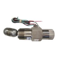
Direct Installation into the Wall of the
Pressure Vessel
1. Determine that the float travel is not
obstructed by the coupling in the
vessel wall, internal baffles, etc.
Do NOT use more than one
float shaft extension P/N
15000478.
2. BE SURE that the float and
extension are tight.
3. Before installing the level
switch, use of a pipe thread
sealant is recommended. Screw
the unit directly into the threaded
connection in the wall of the pressure
vessel.
4. For LS200 and L1
100 be sure that the electrical connection is
positioned at the bottom
.
5. For LS200N the 1/8” NPT pneumatic connection should be on top
(the 3/8” NPT vent connection should be on the bottom) for
service on a “T
rip on Rising” application. The LS200N can be
rotated 180° for service on a “T
rip on Falling” application.
6. Make the electrical wiring connections according to
appropriate wiring diagrams for the alarm or shutdown
system to be used. The electrical connection is 1/2”-14 NPT.
7. BE SURE all electrical connections are insulated and the
cover is fully installed before reconnecting electrical power.
8. BE SURE all pressure connections are tight before
pressurizing the system.
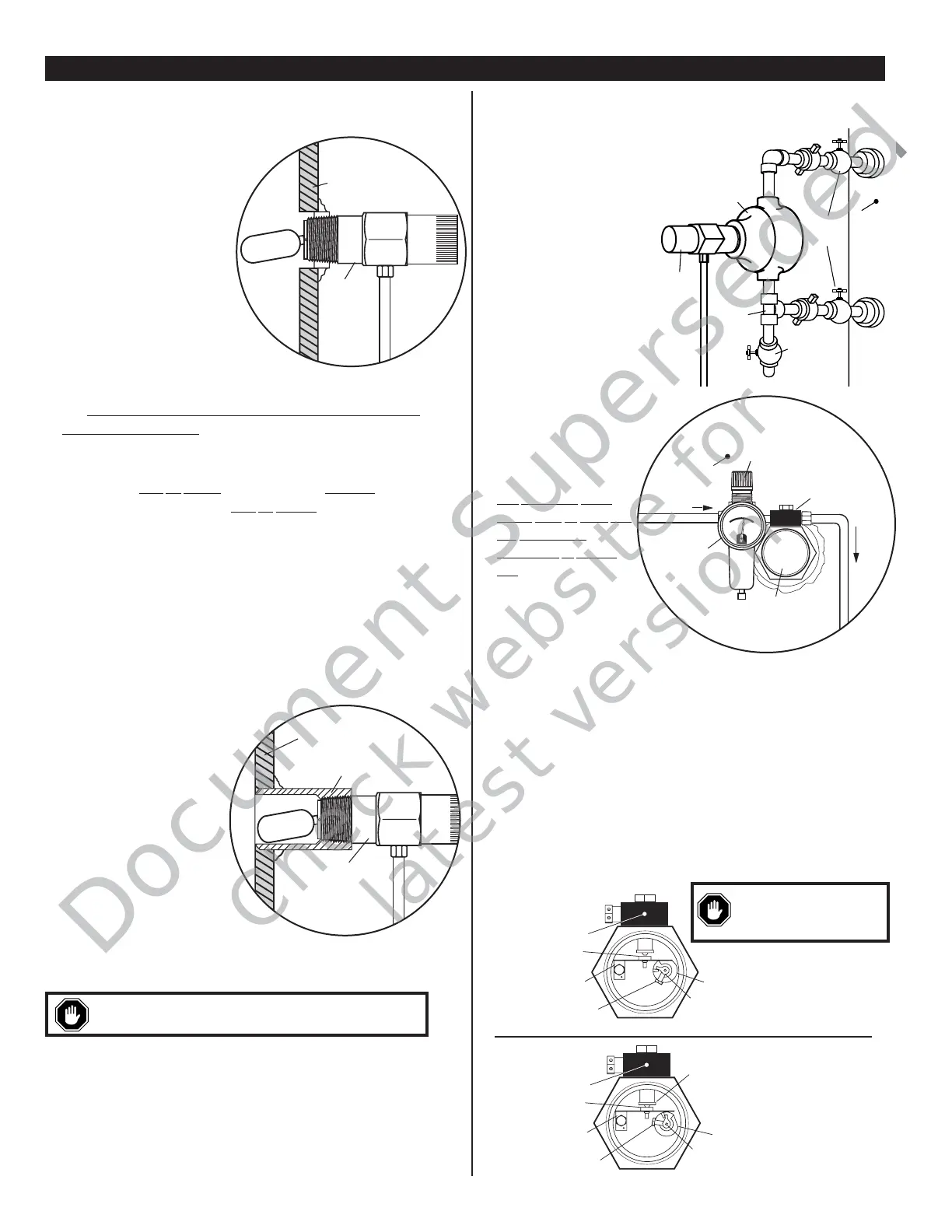
Installation with a Weld Collar
1. The weld collar, P/N 15050375, must be welded into the wall
of the pressure vessel according to
code standards and good
welding practices.
2. Follow above instructions
for installation directly
into the wall of the
pressure vessel.
3. NOTE: Weld collar
15050375 can be used
ONLY with model LS200.
Installation Using
External
Float Chamber 15051098
1. Install the float chamber 15051098 on the outside wall of the
pressure vessel using 1” NPT piping or use the mounting
surface with a bracket. Position the 2” NPT threaded
connection at the height where you want the level switch to
operate. The 2” NPT threaded connection must be positioned
away from the tank wall.
2. A tee and bleed valve are typically installed at the bottom of the lower 1
inch pipe riser to allow draining of the float chamber for servicing or
replacement.
NOTE: A typical installation with Blocking and
Bleed valves is shown at right.
3. Install the LS200 or
LS200N/NDVO/NDVOR
in the 2” NPT connection of
the float chamber.
BE SURE float travel
is not restricted and that
the float is tight onto
the float shaft.
4. To complete installation and
wiring, follow the instructions for
mounting directly into wall of
the vessel and for wiring.
Pneumatic Models
1. All pneumatic models
operate on the vent
principle.
The pneumatic
signal
source must be clean and
dry “Instrument
Quality”
air or natural
gas.
The input pneumatic signal
must be regulated between 30
and 70 psi (207-483 kPa) [2 -4.83
bar].
If produced gas is used as the signal source,
it should be taken after gas passes through the final scrubber.
A suitable filter must be positioned before the LS200NDVO to prevent
liquids and/or particulates from entering the dump valve operator.
NOTE: Check filter periodically for wear and tear and elements
that hamper the flow of the pneumatic signal.
2. All pressure connections must be tight and maintained tight so as
not to leak air/gas.
3. Valve seat adjustment can be made if air/gas begins to leak. Care
should be taken when adjusting as only slight movement is necessary
to stop the leakage; excessive force will bind the seating mechanism.
See the instruction below for adjustment.
PRESSURE VESSEL INSTALLATION: LS200, LS200N and L1100
Turn left until air leakage stops.
adjustment will lockup mechanism.
without obstruction.
 Loading...