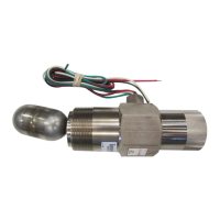
LS-04006N page 3 of 4
REPLACING AND INSTALLING THE DVO ASSEMBLY
Tools Needed: Strap or pipe wrench, 9/16" Hex wrench, tubing
cutters and benders and the appropriate tools for the fittings.
1. Block off and bleed the instrument gas pressure supply to the
LS200NDVO/DVOR.
2. Remove the tubing between the LS200NDVO/DVOR and the
scrubber dump valve, and remove the supply gas tubing
(regulator [-R-] if used).
3. Remove the LS200NDVO/DVOR from the vessel (optional).
4. If the LS200NDVO/DVOR was removed from the vessel,
mount it in a suitable vise on a work bench (if possible).
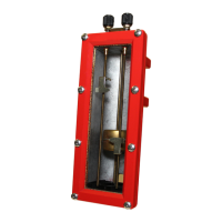
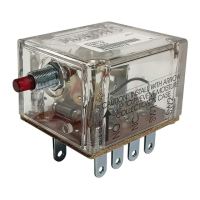
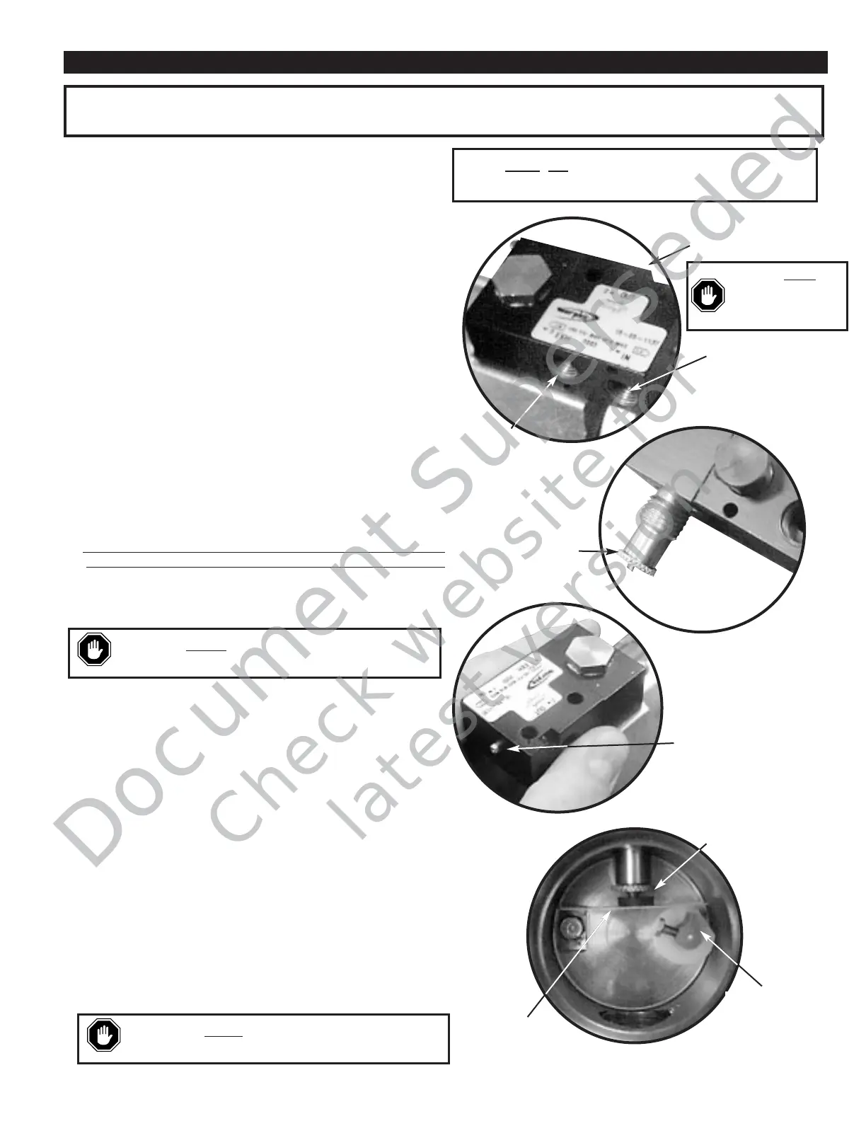
5. Using the proper tools, disconnect the Inlet, Outlet, and Exhaust
fittings from the existing DVO (see fig. 1). You will re-connect
these to the new DVO in a later step.
NOTE: The following steps must be done with the DVO in the
upright position (on top of the LS200NDVO).
6. Remove the LS200NDVO/DVOR cover. The use of a strap
wrench or a pipe wrench may be needed.
7. With a 9/16" hex wrench loosen the hexhead bolt on top of the
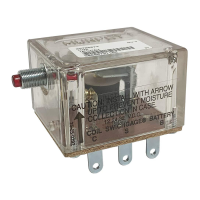
DVO and remove the existing DVO from the body.
8. Ensure that the adjustable orifice is fully raised up to ensure
when inserted into the body that the actuator arm is not bent.
See fig 2.
9. Insert the new DVO onto the body. The DVO manual valve
operator must face away from the vessel.
10. With the DVO aligned over the hex on the LS200NDVO body,
tighten the valve using the 9/16" hex wrench. You may need to
hold the DVO while tightening to keep it from rotating. See fig 3.
11. The pneumatic input signal should be regulated between 30 and
70 psi for proper setting of the adjustable orifice. With the float
in the down position adjust the adjustable orifice down until it
touches the seat (see fig 4). If the DVO is still leaking make
slight adjustments (1/32 turn). Excessive adjustments will lock
up mechanisms. After adjusting make sure float moves freely
up and down.
12. Replace the LS200NDVO/DVOR cover.
13. Using the appropriate tools re-install the Inlet, Outlet, and
Exhaust fittings to the new DVO (see fig 1). Thread sealant is
recommended but care should be used to not allow excess to
enter valve.
14. If the LS200NDVO/DVOR was removed from the vessel re-
install it at this time. Thread sealant is recommended.
15. Connect to the Inlet, Outlet, and Exhaust fittings. According to
installation drawings.
When replacing/installing the DVO assembly, tubing and fitting modifications may be required. We suggest removing the LS200NDVO/DVOR
from the vessel. Relieve pressure from the vessel or use block valves before removing the LS200NDVO/DVOR.
CAUTION:
Ensure that the actuator arm is not bent
during assembly.
CAUTION:
LS200 series parts are not
interchangeable with the L1200 Series.
CAUTION:
LS200
series parts are not
interchangeable with
the L1200 Series.
NOTE:
Clean
,dry instrument quality gas should be used.
Use of filters will improve service life and reliability.
Outlet
Inlet
Exhaust
Figure 4
Figure 2
Replacing and Installing the DVO Assembly
For Models LS200NDVO & LS200NDVOR
Adjustable
Orifice
Figure 3
Orifice
Adjustment
Cam
(Not Adjustable)
Actuator Arm
(Not Adjustable)
Manual Valve
Operator
Figure 1
 Loading...